Speaker
Description
This study focuses on the validation of the probe used in the Near Field Scan (NFS) assessment of electric vehicles (EVs). The validation includes the evaluation of the antenna factor (AF) of the probe: the ratio of the induced voltage to the product of the magnetic field strength and the number of turns as well as the effective area in the loop, the selectivity, the sensitivity and the noise.
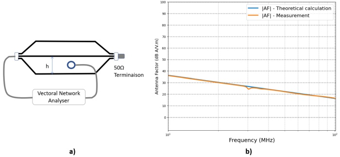
Precise measurements in a transverse electromagnetic (TEM) cell require comprehensive knowledge of the field distribution in the cell. This paper presents the configuration and procedure of a measurement to generate the distribution of electromagnetic fields in TEM cells appropriate for a loop probe and its effective behavior. The measurement data for 3 axes are obtained for the loop probe in a frequency range from 10 MHz to 1000 MHz using a Vector Network Analyzers (VNA), as shown in Fig. 1a. From measured transmission coefficient $S21$, the antenna factor is calculated by
$F_{aH} \, \left[\left(\frac{A}{m} \right)V \right] = \frac{H_{TEM}}{V_{out}}=\frac{\sqrt{\frac{P_{in}\cdot50}{Z_0h}}}{\sqrt{P_{out}\cdot50}} = \frac{1}{S21}\cdot\frac{1}{Z_{0}h}$
The results show a strong agreement with the theoretical calculations, especially at high frequencies. The antenna factor (AF) for the position shows slight variations, which is to be expected as the wavelength approaches the size of the loop probe at such frequencies. This results in the influence of the orientation of the probe and the effective loop circumference, as shown in Fig. 1b.

Fig. 1 a) Measurement Configuration In A TEM Cell. b) Magnetic Loop probe Antenna factor as a function of the frequency.
We arrange the investigated probes in two different directions within the cell and quantify the transmission parameter $S21$ in all scenarios. In a first orientation, the probe is positioned so that the surface of the loop is perpendicular to the Y-axis; in the second, as can be seen, the probe is rotated 90 degrees around the Z–axis, the measurement is totally changed with respect to the theoretical calculation.
References
[1] R. Trip and A. Buta, “TEM Cell Measurements in Automotive EMC : A Case Study,” 2022 Int. Symp. Electron. Telecommun., pp. 1–4, 2022, doi: 10.1109/ISETC56213.2022.10010216.

