The XIV European Magnetic Sensors and Actuators Conference
Lecture Hall
Košice, Slovakia
We are glad to announce that the XIV. European Magnetic Sensors and Actuators Conference (EMSA 2024) will take place in Kosice from 24th to 27th June of 2024 at the University of Pavol Jozef Safarik in Kosice, Slovakia, located in the very center of Kosice city.

The European Magnetic Sensors and Actuators Conference (EMSA) is a consolidated European forum that serves to assess the status, recent progress, and development in the field of magnetic sensor technology and magnetic actuators. It was first held in 1996 in Iasi (Romania) and since then has continued every two-three years in different European cities. The aim of the conference is to generate an overview of research in magnetic sensors and actuators, to recognize their relevance in modern industry and to identify potential future collaborations. EMSA 2024 will provide an excellent opportunity to bring together scientists and engineers from universities, research institutes and industry to present and discuss their most recent results covering both fundamental and applied aspects of magnetic sensors and actuators.
Conference topics:
- Novel magnetic materials
- Modelling and simulation
- Magnetic sensors
- Magnetic actuators
- Magnetic MEMS
- Biomedical Applications of sensors and actuators
- Applications of spin phenomena
- Other applications
- Metrology
We hope this Conference will reach the high scientific level and the careful organization of the previous EMSAs.
We are looking forward to your scientific contribution.
See you in June 2024!!!
prof. R. Varga
(on behalf of organizing committee)
-
-
16:00
→
18:00
Registration 2h Lecture Hall
Lecture Hall
Košice, Slovakia
Doktora Kostlivého 576/1 -
18:00
→
21:00
WELCOME party 3h MINERVA
MINERVA
Doktora Kostlivého 576/1
-
16:00
→
18:00
-
-
08:00
→
09:00
Registration 1h Lecture Hall
Lecture Hall
Košice, Slovakia
Doktora Kostlivého 576/1 -
09:00
→
09:10
Opening ceremony 10m Lecture Hall
Lecture Hall
Košice, Slovakia
Doktora Kostlivého 576/1 -
09:10
→
09:30
EMSA History & Future 20m Lecture Hall (Košice)
Lecture Hall
Košice
Doktora Kostlivého 576/1Speaker: Evangelos Hristoforou (Sensors Lab, National Technical University of Athens) -
09:30
→
10:30
TUE: Session 1 Lecture Hall
Lecture Hall
Košice, Slovakia
Doktora Kostlivého 576/1Convener: Pavel Ripka (CVUT FEL (Czech Technical University, Faculty of Electrical Engineering))-
09:30
Low Noise Magnetoelectric Composite Sensors 30m
Magnetic field sensors are devices that detect and measure magnetic fields around permanent magnets, electrical conductors, and electrical devices. As such, they are particularly relevant for applications in IoT, 5G, smartphones, energy, and biomedical engineering. In this context, dedicated research is being carried out on novel thin film composite magnetoelectric (ME) sensor concepts for the detection of magnetic fields down to the picotesla range. Advanced wide-field magneto-optical Kerr effect microscopy with high temporal resolution is used to study local effects in operating ME composite sensor structures. Together with supporting electrical measurements, the realized magnetospatial analysis of working devices sheds light on magnetization changes due to domain nucleation, domain wall resonances, domain wall bending modes, and spin-wave-like phenomena. Each of these is specific to different types of composite ME sensors, ranging from resonance to modulated to $\Delta E$ to SAW sensor systems. Complementary electrical noise and detection limit analyses reveal the different noise mechanisms, electrical and magnetic, for the different sensors. By understanding the complex magnetic interactions, strategies and implementations are identified to optimize magnetic sensor structures.
The design and application of flux closing magnetic multilayer structures with minimal noise is discussed. Magnetostatically stabilized but still responsive single magnetic domain layers are the basis for low noise sensors due to the absence of magnetic domain walls. Limits for sensitivity enhancement from additional magnetoelastic domain effects will be discussed. Beyond magnetic domain engineering, other schemes of magnetic noise suppression, based on a combination of sensing and pinning magnetic multilayer stacks are demonstrated. By introducing special magnetic sensing layers the influence of the electrical carrier signal to noise is virtually eliminated. The magnetically enforced reduction of the electrical background signal paves the way for ultra-low noise ME sensor applications capable of detecting picotesla magnetic fields. We show that with the current approaches and beyond magnetic domain activity, we are seeing novel effects based on non-linear magnetoelastic effects. Low noise sensor detectabilities are now approaching fundamental limits.
Acknowledgements
Funding by the DFG for the CRC 1261 “Magnetoelectric Sensors: From Composite Materials to Biomagnetic Diagnostics” is highly acknowledged.
References
[1] L. Thormählen et al., “Low-noise inverse magnetoelectric magnetic field sensor,” Applied Physics Letters, vol. 124, no. 17. AIP Publishing, Apr. 22, 2024. doi: 10.1063/5.0196637.
[2] E. Spetzler, B. Spetzler, and J. McCord, “A Magnetoelastic Twist on Magnetic Noise: The Connection with Intrinsic Nonlinearities,” Advanced Functional Materials, vol. 34, no. 9. Wiley, Nov. 20, 2023. doi: 10.1002/adfm.202309867.
[3] V. Schell et al., “Exchange biased surface acoustic wave magnetic field sensors,” Scientific Reports, vol. 13, no. 1. Springer Science and Business Media LLC, May 25, 2023. doi: 10.1038/s41598-023-35525-6.
[4] C. Müller et al., “Imaging of Love Waves and Their Interaction with Magnetic Domain Walls in Magnetoelectric Magnetic Field Sensors,” Advanced Electronic Materials, vol. 8, no. 6. Wiley, May 04, 2022. doi: 10.1002/aelm.202200033.
[5] P. Durdaut et al., “Phase Noise of SAW Delay Line Magnetic Field Sensors,” Sensors, vol. 21, no. 16. MDPI AG, p. 5631, Aug. 21, 2021. doi: 10.3390/s21165631.Speaker: Jeffrey McCord (Kiel University) -
10:00
Limitation in Ni2FeGa Microwires Design as Sensor/Actuator with Focus on Shape Memory Effect 15m
The microwires due to their dimensions have a huge potential in wide fields from agricultural, medical, and technological high-end applications such as sensors or actuators. On the one hand, designing different types of materials for each application is possible. On the other hand, there is the scalability of dimensions, which brings opportunities to control the physical properties of the microwire material [1].
One of the interesting candidates among microwires is the Heusler alloy, specifically Ni$_2$FeGa. In this alloy takes place the phase transformation from a high-temperature ordered phase to a low-temperature phase. Since the transformation is thermos-elastic, the alloy exhibits a shape memory phenomenon. It is already known that the temperature range of phase transformation could be changed from 50 K up to 400 K by fine-tuning the alloy chemical composition [2]. Setting the transformation temperature, which affects material's sensitivity to the change in its magnetic properties, is very important for its applicability. This work will present the influence of chemical composition tuning on the microstructure, phase transformation temperature (see Fig. 1), physical properties, and limitations of the shape memory effect.
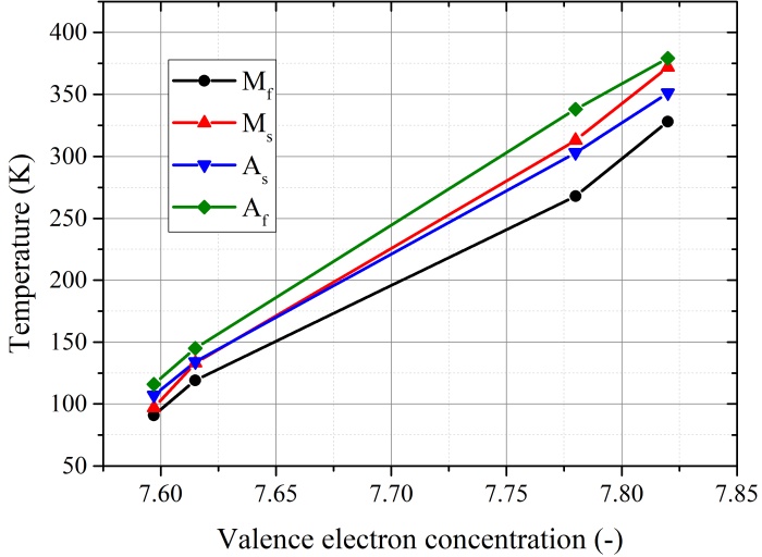
Fig. 1 The transformation temperature in dependence on valence electron concentration.
Acknowledgements
This work was supported by Slovak VEGA 2/0086/22 and VEGA 1/0180/23.
References
[1] R. Jurc et al, “Sensoric application of glass-coated magnetic microwires“, (2020) Magnetic Nano- and Microwires: Design, Synthesis, Properties and Applications, 2020, pp. 833-868. doi: 10.1016/B978-0-08-102832-2.00028-1.
[2] M. Hennel, L. Galdun, R. Varga, “Analysis of magnetocaloric effect in Ni2FeGa-based glass-coated microwires”, Materials, vol. 560, art. no. 169646, Oct. 2022. doi: 10.1016/j.jmmm.2022.169646.Speaker: Ondrej Milkovic (Institute of Materials Research, Slovak Academy of Sciences) -
10:15
Mobile Robots based on Multipole Magnetoactive Elastomer for Controllable Planar Locomotion 15m
Magnetoactive elastomers (MAEs) consist of an elastic matrix with embedded micron-sized soft and/or hard magnetic particles. Such elastomers change their mechanical and rheological properties under the influence of external or internal magnetic fields. The magnetization of MAEs with hard magnetic particles in a strong magnetic field enables to produce elastic permanent magnets.
Magnetized MAEs are promising for use in the field of soft robotics. Motion systems realized using MAEs can achieve movement with a minimum number of actuators. In this work, the locomotion systems are made of a special type of MAEs as a functional element. We use beam-shaped MAEs, which are synthesized from a mixture of hard and soft magnetic particles. The MAE beams are permanently magnetized in a way that there is a south pole in the middle and a north pole at each end. The motion principle of the locomotion systems is based on the magnetic-field-induced bending deformation of the magnetized beam. The alternating magnetic field causing the beam deformation is generated by an electromagnetic coil integrated into the robot’s casing. Silicone bristles on the underside of the MAE beam provide asymmetrical friction conditions. Due to the cyclic interplay of friction forces and inertial forces caused by periodic bending, the robot shifts its position in each cycle and thereby moves forward. The movement speed is strongly dependent on the actuating frequency, with a maximum speed being achieved in the resonance range [1]. The use of two MAE functional elements, that are positioned parallel and mirror-symmetrical to each other, enables movement in a plane (Fig. 1). The principle of skid-steer is utilised. The movement speed along a curved path is determined by the choice of two actuating frequencies of the coils. The developed locomotion systems demonstrate good maneuverability and controllability. Their actuation method makes it easy to change the translational speed and yaw angle, making such systems suitable for use in complex operating conditions.

Fig. 1 Locomotion system for planar movement, left: top view, right: side view.
Acknowledgements
The work is funded by the Deutsche Forschungsgemeinschaft (DFG), project BE-6553/2-1.
References
[1] M. Reiche, T. I. Becker, G. V. Stepanov, and K. Zimmermann, “A Multipole Magnetoactive Elastomer for Vibration-Driven Locomotion,” Soft Robotics, vol. 10, no. 4. Mary Ann Liebert Inc, pp. 770–784, Aug. 01, 2023. doi: 10.1089/soro.2022.0106.
Speaker: Marius Reiche
-
09:30
-
10:30
→
11:00
Coffee break 30m MINERVA
MINERVA
Doktora Kostlivého 576/1 -
11:00
→
12:30
TUE: Session 2 Lecture Hall
Lecture Hall
Košice, Slovakia
Doktora Kostlivého 576/1Convener: Marco Coïsson (INRIM)-
11:00
Low Noise Fluxgate Sensors for Biomedical Applications 30m
Biomedical applications typically require very low noise magnetic sensors, since the magnetic field to be measured are usually very small. Traditionally SQUIDs have been the only sensors able to reach noise levels low enough to be employed in this field. However, the necessity of cryogenic temperature limits the applications of these sensors to fields where extremely low noise is required. Meanwhile, during the last lustra the noise of other sensors have been strongly reduced until becoming competitive in fields like magnetocardiography where tens of pT in a bandwidth from 1 Hz to few tens of Hz is required. Among them orthogonal fluxgate have shown remarkable results achieving noise well below 1 $\mathrm{pT}/\sqrt{Hz}$ in the bandwidth of interest [1]. One of the advantages of orthogonal fluxgates is the high spatial resolution which, together with the low cost allowed to create a matrix of sensors to map the magnetic field produced by a human heart [2].
In this contribution I will present how it was possible to achieve these results. Starting from the requirements for magnetocardiography (MCG) diagnostic and in particular the necessity to measure the T wave on a large number of points, I will present the methods used to achieve low noise magnetometer with high spatial for MCG. These include the development of a composition for amorphous Co-rich magnetic microwires which retain low magnetostriction when annealed to increase their circular anisotropy; this is obtained by decreasing the amount of iron so that the negative magnetostriction becomes close to zero after annealing. I will present the dependence of the noise on the geometry of the sensor and in particular how to increase the spatial resolution in the axis of the sensor without causing an excessive increase of noise. Unexpectedly, even using multiple shorter coils on the same core does not significantly increase the noise.
A very important aspect of biomagnetic fields is that they rapidly decay in space, therefore one my be lead to believe that, for instance, just a few cm far from the chest the MCG signal is vanishing and not measurable. From this point of view we show how the ferromagnetic core of the fluxgate acts as a flux concentrator which carries the signal even at several centimeters far from the chest making it measurable. An important focus will be given to the electronic which creates low noise excitation current for the sensors, as well as amplify and demodulate the signal from the pick-up coil and how this was designed to minimized the noise of the magnetometer. In particular, I show how a proper design of the preamplifier can reduce the current absorbed by the coil and return higher sensitivity contributing to decrease the noise floor of the sensor.
Another important aspect of the implementation of orthogonal fluxgates for real-life applications like MCG is the manufacturing process of the sensor itself. Traditionally fluxgates are known to have a low noise only on few samples over a large batch of produced sensors. Since applications like MCG require a large number of sensors with low cost it would not be feasible to use this technology unless a very high yield ratio. I will show how we managed to achieve a yield larger than 95 $\%$ on batch of serially produced sensor, proving that the technology is ready for mass implementation. Finally I will also discuss the limitations of this technology with special regard to offset stability with temperature and how, however, this limitations can be mitigated when not directly corrected.
Speaker: Mattia Butta Gonzales (Faculty of Electrical Engineering, Czech Technical University in Prague) -
11:30
Development of Planar Hall Magnetoresistive Sensor and its Application for Magnetic Encoder 15m
Performance of planar Hall magnetoresistive (PHMR) sensors was measured in different specification, such as sensor layer thickness, geometry [1]. We figured out the change in PHMR sensor performance for each factors and applied into magnetic encoder experiments. In this magnetic encoder experiments, PHMR sensor was located near to steel gear and permanent magnet was located behind the PHMR sensor to induce stray field from magnetized steel gear. Signal from PHMR sensor was compared in different factors, such as distance between gear-sensor, distance between sensor-magnet or direction of sensor and magnet, etc. Total harmonic distortion (THD), signal amplitude and phase difference were main performance requirements, but those are not satisfied in our traditional multi-ring type NiFe/IrMn bilayer sensors. New ferromagnetic material and sensor geometry were applied to encoder sensors to enhance the main performance requirements and the experimental result was discussed in this speech.
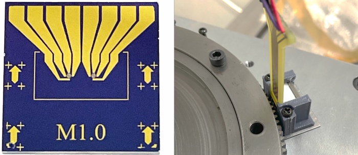
Fig. 1 Optical microscope image of PHMR sensor (left) and magnetic encoder using PHMR sensor (right).
Acknowledgements
This research was supported by a National Research Foundation (NRF) grant funded by the MSIT (Grant No. NRF-2018R1A5A1025511).
References
[1] T. Jeon et al., “Operational Parameters for Sub-Nano Tesla Field Resolution of PHMR Sensors in Harsh Environments,” Sensors, vol. 21, no. 20. MDPI AG, p. 6891, Oct. 18, 2021. doi: 10.3390/s21206891.
Speaker: Taehyeong Jeon (Daegu Gyeongbuk Institute of Science and Technology) -
11:45
Investigating Neutron Radiation Induced Damage on Novel Type of Hall-Effect Sensors 15m
Our research explores the potential use of semiconductor thin-film materials and graphene-based structures for magnetic field detection in harsh environments, particularly in thermonuclear reactors. We have conducted preliminary research to investigate the impact of high temperature [1] and neutron irradiation [2,3] on the electrical properties of these sensors. Our studies involved a 2D material made from hydrogen-intercalated quasi-free-standing graphene on semi-insulating 4H-SiC (0001), passivated with an Al$_2$O$_3$ layer [4], and a donor-doped InSb-based thin-film on a semi-insulating GaAs substrate [2]. Our research has shown how described systems were affected by fast neutron fluence of $7\times 10^{17}$ cm$^{-2}$ using MARIA research nuclear reactor. Based on Hall effect measurements and micro-Raman analysis, we conjecture that for graphene-based structure after irradiation, the primary factor impacting the electrical characteristics is the depletion of atoms in the hydrogen layer. This phenomenon is expected to decrease the surface area of intercalation which becomes too scarce to support graphene separation. However, we observe self-healing abilities at temperatures higher than 200 $^{\circ}$C [3]. To determine if these materials are suitable for magnetic field sensing in thermonuclear reactors, we need to understand how they will be affected by stronger neutron radiation. Therefore, we investigate new modes of damage in 5 times greater neutron fluence ($40\times 10^{17}$ cm$^{-2}$) and how the effects of neutron irradiation differ when the graphene-based sensor’s substrate polytype is changed to 6H-SiC (0001).
Acknowledgements
The research has received funding from the National Centre for Research and Development under Grant Agreement No. LIDER/8/0021/L-11/19/NCBR/2020 for project MAGSET and partly from the Ministry of Education and Science (Poland) under Project No. 0512/SBAD/2420.
References
[1] W. Reddig, et al., “High-Temperature Stability of Sensor Platforms Designed to Detect Magnetic Fields in a Harmful Radiation Environment,” IEEE Sensors Letters, vol. 7, no. 8, Aug. 2023, doi: 10.1109/LSENS.2023.3297795.
[2] S. El-Ahmar et al., “The Comparison of InSb-Based Thin Films and Graphene on SiC for Magnetic Diagnostics under Extreme Conditions,” Sensors, vol. 22, no. 14, p. 5258, Jul. 2022, doi: 10.3390/s22145258 .
[3] S. El-Ahmar et al., “Graphene on SiC as a promising platform for magnetic field detection under neutron irradiation,” Applied Surface Science, vol. 590, p. 152992, Jul. 2022, doi: 10.1016/j.apsusc.2022.152992.
[4] T. Ciuk et al., “Defect-engineered graphene-on-silicon-carbide platform for magnetic field sensing at greatly elevated temperatures,” Carbon Trends, vol. 13, no. October, p. 100303, Dec. 2023, doi: 10.1016/j.cartre.2023.100303.Speaker: Wiktoria Reddig (Poznan University of Technology) -
12:00
Inductive Microsensor for Biomedical Analysis by Magnetic Nanoparticles Detection 15m
Developing portable sensors is crucial for improving the detection of biological agents. These devices enable rapid, on-site analysis, providing real-time monitoring that is vital for applications such as disease diagnosis and environmental monitoring or the pathogen detection including viruses and bacteria. Portable sensors are compact, lightweight, and easy to use, making them suitable for deployment in various settings, including remote areas and healthcare facilities. By leveraging advanced technologies, these sensors offer high sensitivity and specificity, facilitating timely detection and response to potential threats, thereby enhancing public health and safety. In this context, the use of sensors based on magnetic nanoparticles proves to be particularly relevant [1].
This paper proposes to investigate an innovative inductive microsensor for multipathogen detection based on magnetic nanoparticles (MNPs) fluid integrated into a microfluidic chip platform. The nonlinear detection process employs Faraday’s law, which relates the voltages measured in intermodulation peaks with the magnetic frequency mixing method [2]. This method couples a low frequency ($f_{LF}$) and a high frequency ($f_{HF}$), capitalizing on the nonlinear response of MNPs with diverse sizes and magnetic properties to dual-frequency excitation. Multiphysics simulations including a magnetic shimming analysis have been performed to optimize the parameters of the microsensor, ensuring its optimal performance. Additionally, experimental validation for $f_{LF}$=64 Hz and $f_{HF}$ =40 kHz and MNPs constituted of Fe$_2$O$_3$ S540 with 20 nm of size is conducted to confirm the results obtained from simulations. Figure 1 illustrates the levels of intermodulation peaks acquired, with the first and second peaks serving as reference points utilized to extract the quantity of detected biological agents.
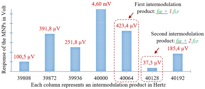
Fig. 1 Experimental results of Fe$_2$O$_3$ S540 20nm MNPs detection.
References
[1] A. Sobczak-Kupiec, et al, “Magnetic nanomaterials and sensors for biological detection, ” Nanomedicine: Nanotechnology, Biology and Medicine, vol. 12, no. 8, pp. 2459-2473, Nov. 2016 doi : 10.1016/j.nano.2016.07.003.
[2] H-J Krause et al,“Magnetic particle detection by frequency mixing for immunoassay applications, ”Journal of Magnetism and Magnetic Materials, vol. 311, no.1, pp. 436-444, April 2017 doi: 10.1016/j.jmmm.2006.10.1164.Speaker: Mr Samy Alati (Sorbonne Université, CNRS, Laboratoire de Génie Electrique et Electronique de Paris, 75252, Paris, France Université Paris-Saclay, CentraleSupélec, CNRS, Laboratoire de Génie Electrique et Electronique de Paris, 91192, Gif-sur-Yvette, France) -
12:15
Magnetoelastic Resonators Functionalized with Metal Organic Frameworks for Wireless Humidity Detection 15m
Among other gases, the detection of relative humidity (RH) is crucial in air quality monitoring, food storage or industrial processes control. We present here a wireless humidity sensor based on the magnetoelastic resonance (MER) phenomenon. MER sensors are usually made of magnetostrictive ribbons, which can be driven to mechanical resonance via magnetic field excitation. The basis of their operation is the high sensitivity of their resonance frequency ($f_r$) to different factors, such as the changes in the resonator mass: $\Delta f_r/f_{r0}= -\Delta m/2m_0$ [1]. As their excitation and detection are conducted magnetically, they result especially interesting for remotely detect humidity in closed or inaccessible environments. To provide the MER sensors with water absorption capacity (mass gain $\Delta m$, and thus a detectable change in $f_r$), we propose their functionalization with active layers of water-adsorbent Metal-Organic Framework (MOF) materials (Figure 1a) [2]. MOFs are built by metal ions and organic ligands assembled in 3-dimensional structures, and stand out among the adsorbent materials because of their high porosity, great surface area, tunable pore volume, and tailored selectivity.
Five MOFs with different water-adsorption behavior were synthetized: MOF-801, MOF-808, UiO-66-NH2, Al-Fumarate and CAU-23, and then deposited on the resonator (Fe$_{73}$Cr$_{5}$Si$_{10}$B$_{12}$) surface by spray coating technique. The response of the functionalized sensor (MER resonator + MOF coating) to different levels of humidity was assessed over controlled N$_{2}$/H$_{2}$O flows. The tested MOFs showed promising water harvesting capacity, enabling a successful sensor response to humidity cycles in a wide RH range: 3-85 $\%$ (Figure 1b). MOF water absorption capacity and overall performance of the MER/MOF sensors (sensitivity, stability and selectivity to water molecules) were evaluated. The response time of the devices was about 15 seconds, with stabilization and recovery times in adsorption and desorption processes of less than 1 minute for certain RH ranges. In addition to their solid performance as gas sensors, in our work we found magnetoelastic resonators to be a promising tool for the characterization of the dynamic adsorption capacity of MOF materials (water uptake per g), as they easily provide a quantitative measure of the mass of water adsorbed by the material.
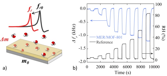
Fig. 1 a) Principle of operation of the MER sensor + MOF layer for humidity detection. b) Response of the sensor with MOF-801 layer to cycles of adsorption and desorption of H$_{2}$O at different humidity levels ($\%$ RH), and comparison with reference sensor (Sensirion SHT45).
References
[1] C. Grimes et al., “Wireless Magnetoelastic Resonance Sensors: A Critical Review,” Sensors, vol. 2, no. 7. MDPI AG, pp. 294–313, Jul. 23, 2002. doi: 10.3390/s20700294.
[2] H. Yuan et al., “Metal-Organic Framework Based Gas Sensors,” Advanced Science, vol. 9, no. 6, p. 2104374, Feb. 2022, doi: 10.1002/ADVS.202104374.Speaker: Beatriz Sisniega (Universidad del País Vasco (UPV/EHU))
-
11:00
-
12:30
→
14:00
LUNCH 1h 30m SOKRATES
SOKRATES
Doktora Kostlivého 576/1 -
14:00
→
15:45
TUE: Session 3 Lecture Hall
Lecture Hall
Košice, Slovakia
Doktora Kostlivého 576/1Convener: Nicoleta Lupu (National Institute of Research and Development for Technical Physics, Iasi, Romania)-
14:00
MR Sensors Integration with Soft Magnetic Elastomers for Tactile Applications 30m
Composite magnetic materials have been explored for several applications ranging from biomedical to robotics [1]. The ability to incorporate homogeneous and dense nanoparticles in elastomer matrix creates opportunities for the integration with magnetic sensors in flexible electronics [2], providing viable for large area applications. In addition, biocompatibility between the elastomers and liquid interfaces have been explored in magnetic cytometry [3] and tactile sensors for harsh environment applications [4].
In this work, we will discuss the integration of magnetoresistive (TMR) sensors in tactile sensors, and demonstrated in surface texture and environment exploration. The use of magnetic elastomer cilia, able to recognize bending upon touch, in x and y directions, using two pairs of magnetic sensors, sensitive in both directions enables to detect $H_{x}$ and $H_{y}$ [5], for a comprehension of the actions over the sensor surface. The magneto-mechanical model for the cilia bending upon touch is presented, so to obtain values for the pressure from the bending angle. A distributed architecture is also presented, where the sensor point location translates the variations in the field mapping distribution over a 2D surface of an elastomer (continuous skin model). Here a point contact action will deform the field matrix, and the 1D or 2D sensors will identify the application point and orientation of the applied force.References
[1] D. Makarov, M. Melzer, D. Karnaushenko, and O. G. Schmidt, “Shapeable magnetoelectronics,” Applied Physics Reviews, vol. 3, no. 1. AIP Publishing, p. 011101, Mar. 2016. doi: 10.1063/1.4938497.
[2] J. Gaspar et al., “Flexible Magnetoresistive Sensors Designed for Conformal Integration,” IEEE Transactions on Magnetics, vol. 53, no. 4. Institute of Electrical and Electronics Engineers (IEEE), pp. 1–4, Apr. 2017. doi: 10.1109/tmag.2016.2623669.
[3] S. Cardoso et al., “Challenges and trends in magnetic sensor integration with microfluidics for biomedical applications,” Journal of Physics D: Applied Physics, vol. 50, no. 21. IOP Publishing, p. 213001, Apr. 27, 2017. doi: 10.1088/1361-6463/aa66ec.
[4] A. Alfadhel and J. Kosel, “Magnetic Nanocomposite Cilia Tactile Sensor,” Advanced Materials, vol. 27, no. 47. Wiley, pp. 7888–7892, Oct. 21, 2015. doi: 10.1002/adma.201504015.
[5] P. Ribeiro, M. Neto, and S. Cardoso, “Strategy for Determining a Magnet Position in a 2-D Space Using 1-D Sensors,” IEEE Transactions on Magnetics, vol. 54, no. 11. Institute of Electrical and Electronics Engineers (IEEE), pp. 1–5, Nov. 2018. doi: 10.1109/tmag.2018.2851928.Speaker: Susana Freitas (INESC-Microsistemas e Nanotecnologias and Instituto Superior Tecnico, ULisboa, Portugal) -
14:30
Lithography Optimization with the Use of Artificial Intelligence for Tunneling Magnetoresistive Sensor Fabrication 15m
When designing a magnetic tunnel junction (MTJ) sensor, Key Performance Indicators (KPIs) such as sensitivity, linear operating field range and electrical resistance are set by the application specifications. One of the critical design parameters to tune is the geometry of the MTJ device, as shape, dimension, and aspect ratio directly impact KPIs [1]. By choosing the geometry of the device, it is possible to fit its operation method to the purpose of the sensor (e.g. high linear range vs. high sensitivity applications) (Fig. 1a). For the patterning of MTJ’s in an industrial setting, mask aligner lithography serves as a cost effective technique for increased throughput and resolution up to 1 $\mu$m. However due to the nature of shadow printing, mask aligner lithography is prone to undesired effects such as dark erosion. This leads to different shape geometry and dimensions having varying optimal lithography conditions (Fig. 1b). Therefore there is a need of determining the optimal conditions when patterning a new shape and having a tailored response on demand.
In this research several machine learning models were trained with data from 35 lithography tests comprising different shapes and patterned with diverse conditions, to ultimately predict the dimensions and the quality of the patterned shape. The quality was defined as the proportion of area affected by dark erosion to the desired shape. To compare the models’ performance two metrics were used, root mean squared error (RMSE) (for normalized data) and the correlation of determination (R2) for each of the outputs of the models. The best performing models obtained were a Gradient Boosted Tree (GBT) with an average RMSE of 0.19 and an average R$^2$ of 0.86, and a Neural Network (NN) with an RMSE of 0.21 and an R$^2$ of 0.81. While the NN performs worse than the GBT model, the NN was chosen for the inverse analysis due to the nature of GBT, as it finds several conditions leading to the same output, hindering the performance of heuristic optimization algorithms during the inverse search.
Once the best performing model was chosen, inverse analysis was performed with the use of heuristic optimization algorithms such as differential evolution, genetic algorithm, and particle swarm optimization, allowing for the prediction of the optimal lithography conditions to obtain a certain pattern. The structure of the model is shown in Fig. 1c. Obtained predictions were compared with the prediction from the GBT model and if both models were in accordance the conditions were then validated with experimental tests.
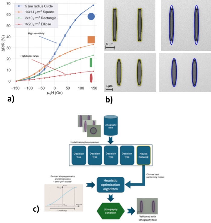
Fig. 1 a) Transfer curves from 4 MTJ devices with different shapes and same magnetic stack. b) Top: 2$\times$20 $\mu$m ellipse with significant dark erosion. Bottom: 3$\times$20 ellipse with reduced dark erosion. Exposed with same conditions. c) Model structure.
References
[1] A. V. Silva, D. C. Leitao, J. Valadeiro, J. Amaral, P. P. Freitas, and S. Cardoso, “Linearization strategies for high sensitivity magnetoresistive sensors,” The European Physical Journal Applied Physics, vol. 72, no. 1. EDP Sciences, p. 10601, Oct. 2015. doi: 10.1051/epjap/2015150214.
Speaker: Daniel Sorensen (Instituto Superior Técnico, INESC MN) -
14:45
Modeling Torques in Systems with Spin-Orbit Coupling 15m
Spin-orbit torque (SOT) provides a fast and efficient way to manipulate the magnetization in magnetic devices such as magnetoresistive random access memory (MRAM) [1]. These devices take advantage of the strong spin-orbit coupling (SOC) in the bulk or at the interfaces of heavy metal (HM) layers to generate spin polarized currents. The spin currents are injected into an adjacent ferromagnet (FM), where through spin dephasing the spins align with the magnetization while exerting a torque on the magnetization. In the bulk, the spin currents are generated through the spin Hall effect (SHE) which generates out-of-plane spin currents with in-plane polarization. The HM/FM interface plays a crucial role in the resulting torques as spin-flip scattering can be strong and additional spin currents can be generated through the Rashba-Edelstein effect (REE) at the interface [2]. Typically, the SOTs are modeled by assuming that the spins instantly align with the magnetization in the FM. In this picture, the SOT is determined purely by the spin current on the HM side of the interface, and the interface scattering is captured by the complex spin mixing conductance.
We compare this approach with one that allows for transmission of the transverse spin currents into the bulk by introducing a transmission spin mixing conductance. Furthermore, we explore the addition of the REE through considering spin-flip scattering from a Rashba SOC potential at the interface. In Fig. 1 we show that these two approaches give qualitatively similar results, and with parameter fitting the instant absorption assumption can be a good approximation for bilayers. The addition of the REE yields a stronger field-like torque which does not vanish with decreasing HM thickness in agreement with reported experimental results [3].

Fig. 1 HM thickness dependence of the spin torque in a HM($d_{HM}$)/FM(1.2 nm) bilayer induced by a $10^{12}$A/m$^2$ electrical current. Panel (a) and Panel (b) show the torque generated by the SHE and by both the REE and the SHE, respectively. Dashed lines show the result obtained from considering instant absorption of transverse spin currents.
References
[1] S. Hu et al., “Frontiers in all electrical control of magnetization by spin orbit torque,” Journal of Physics: Condensed Matter, vol. 36, no. 25. IOP Publishing, p. 253001, Mar. 27, 2024. doi: 10.1088/1361-648x/ad3270.
[2] V. P. Amin, P. M. Haney, and M. D. Stiles, “Interfacial spin–orbit torques,” Journal of Applied Physics, vol. 128, no. 15. AIP Publishing, Oct. 21, 2020. doi: 10.1063/5.0024019.
[3] A. Ghosh, K. Garello, C. O. Avci, M. Gabureac, and P. Gambardella, “Interface-Enhanced Spin-Orbit Torques and Current-Induced Magnetization Switching of Pd/Co/AlOx Layers,” Physical Review Applied, vol. 7, no. 1. American Physical Society (APS), Jan. 06, 2017. doi: 10.1103/physrevapplied.7.014004.Speaker: Victor Sverdlov (CDL for NovoMemLog, IuE, TU Wien) -
15:00
Effect of Topography on Extraordinary Magnetoresistive Devices 15m
Magnetoresistive magnetic sensors play a key role in sensing magnetic fields at room temperature, with applications spanning from information storage to biomagnetism. Extraordinary magnetoresistive (EMR) sensors are a promising class of magnetoresistive sensors, which exhibit a magnetoresistance on the order of $7.5\times 10^5\,\%$ at 4T [1]. The extraordinary magnetoresistance is a geometrical effect arising from a field-dependent change in the current paths in devices consisting of two materials with different conductivities. As the effect is very sensitive to the device's geometry, finite element simulations are often used to optimize and predict the performance prior to sensor fabrication. In simulations, however, EMR devices are often assumed flat, unlike real devices, where deposition techniques often result in devices with significant topography.
Here, we consider this topography explicitly by numerically studying metal-semiconductor EMR devices with different 3-dimensional topographies. We vary the geometry of the inner metallic region such as its height and sidewall width because such topographies are usually realistic in sensor production. We show that modeling the 3-dimensional geometry of the EMR sensor is important for capturing the experimental data, as our 3-dimensional numerical model results in good agreement with experimental data [1], exhibiting a low relative error of 4.5 $\%$ for the resistance at 0 T. When using traditional 2-dimensional geometries, this error evaluates to a significantly higher 35.8 $\%$. In addition, we present pathways for both simplifying device fabrication and enhancing the magnetoresistance by making active use of the third dimension.
Acknowledgements
We acknowledge the support of Novo Nordisk Foundation Challenge Programme 2021: Smart nanomaterials for application in life-science, BIOMAG Grant NNF21OC0066526.
References
[1] S. A. Solin, T. Thio, D. R. Hines, and J. J. Heremans, “Enhanced Room-Temperature Geometric Magnetoresistance in Inhomogeneous Narrow-Gap Semiconductors,” Science, vol. 289, no. 5484. American Association for the Advancement of Science (AAAS), pp. 1530–1532, Sep. 2000. doi: 10.1126/science.289.5484.1530.
Speaker: Sreejith Sasi Kumar (Technical University of Denmark) -
15:15
How Physics-Informed Neural Networks (PINNs) could be applied in Magnetic Source Localization and Characterization 15m
Physics-Informed Neural Networks (PINNs) are a novel class of neural networks that enable the integration of machine learning and physical laws. This relatively recent algorithmic technology, introduced in 2019, has numerous important scientific applications in engineering sciences, such as real-time simulation, digital twins, inverse computation, and finite element methods.
In this work, we have investigated the contribution of PINNs to 1D/2D magnetic source localization and compared their performance to our classical approaches [3]. Numerical simulation/modeling is not always the optimal solution for physics problems, especially when real-time response is required, simulations are computationally expensive, learning data is available, some parameters of the physical model are unknown or inaccessible for modeling, or when Model Order Reduction (MOR) is needed to develop/implement a multi-physics numerical twin.
Based on this observation, we have studied the performance of PINNs on our 1D/2D benchmark setup and evaluated how it can improve results or accelerate computation times, making it more feasible to apply to scenarios with many sensing elements having complex spatial geometric configurations. Figure 1 compares our classical method [3] with a PINN approach. The relevant parameter is the position error of the magnetic dipole location versus the distance to two sensors, $d$, the sensor noise (defined with $SNR_{m}$ cf. [3]), and a discrepancy in sensor sensitivity.
The main results demonstrate the efficiency of PINNs in modeling the physical system based on a reasonable training dataset. Furthermore, once trained, PINNs surpass the classical method based on minimization functions [3] in terms of computation time, making them a promising approach for real-time applications.
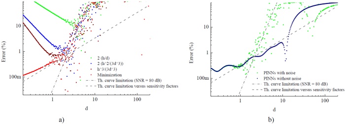
Fig. 1 a) Error in the evaluation of the distance, d, of magnetic dipole to the head of detection based on previous modeling [3], b) errors obtain with PINNs. Both $SNR_{m}$ is 80dB. The PINNs $d$ training range (Log scale - 5 million samples) is given from 0.1 to 10 and the magnetization amplitude, $\mu$, varies from (0.3, 1, 3).
References
[1] M. Raissi, P. Perdikaris, and G. E. Karniadakis, “Physics-informed neural networks: A deep learning framework for solving forward and inverse problems involving nonlinear partial differential equations,” Journal of Computational Physics, vol. 378. Elsevier BV, pp. 686–707, Feb. 2019. doi: 10.1016/j.jcp.2018.10.045.
[2] S. Besnard, F. Jurie, and J. Fadili, “Simpinns: Simulation-Driven Physics-Informed Neural Networks for Enhanced Performance in Nonlinear Inverse Problems,” 2023 13th Workshop on Hyperspectral Imaging and Signal Processing: Evolution in Remote Sensing (WHISPERS). IEEE, Oct. 31, 2023. doi: 10.1109/whispers61460.2023.10430751.
[3] C. Dolabdjian and C. Cordier, “Analysis by Systemic Approach of Magnetic Dipole Source Location Performances by Using an IoT Software Gradiometer Head,” IEEE Sensors Journal, vol. 22, no. 8. Institute of Electrical and Electronics Engineers (IEEE), pp. 7709–7716, Apr. 15, 2022. doi: 10.1109/jsen.2022.3156858.Speaker: Prof. Christophe Dolabdjian (GREYC - Normandie Univ. UNICAEN ENSICAEN CNRS) -
15:30
Four-port Characterization of YIG Magnonic Device: a Way to Improve Magnetic Sensors based on YIG Device 15m
For several years, considerable attention has been devoted to advancing high-sensitivity magnetic sensors to enhance measurement capabilities. A recent trend in this pursuit involves leveraging magnonic devices for sensor construction. While only a limited number of studies have produced and characterized such devices, initial performance outcomes appear promising.
These devices harness the spin wave propagation dependency on external magnetic fields. Typically, Yttrium Iron Garnet (YIG) serves as the magnetic material. The implementation of the sensor system involves several elements. A permanent magnetic field must saturate the material. An rc current passing through an exciting antenna generates spin waves by locally causing a precession of the magnetic moment. A receiving antenna is used to capture the propagated spin wave. A representation of the observed external magnetic field is obtained by demodulating the received signal.
Optimizing this system necessitates the development of a comprehensive model. However, existing physical models primarily focus on spin wave propagation and generation. Our proposed approach adopts a holistic, systemic perspective, treating the sensor element as a four-port coupler (Fig. 1a). This model underscores the intrinsic symmetries of the sensing element and the non-reciprocal nature of spin wave propagation. Notably, our work presents a unified model that accounts for spin wave propagation within microstructured YIG, as well as spin wave reflections along YIG edges, facilitating the assessment of each parameter's impact on the overall system response.
This work presents our latest advancements in the field. Several systems and configurations have been tested, enabling the characterization of various parameters of the couplers. An example of non-reciprocal transmission is provided in Fig. 1b. These results were used to explore new ways to optimize the magnonic sensor.

Fig. 1 a) YIG material and associated antennas, as a four-port network ($a_{e}$ and $b_{e}$ represent incident and reflected power electric wave, $a_m$ and $b_m$ magnetic wave). b) Amplitude of non-reciprocal transmission parameters vs. frequency for a magnetic field $+B_{0}$ (pink), $-B_{0}$ (green), no field (blue), and for antennas alone (red).
Speaker: Sébastien Saez (Normandie Univ, UNICAEN, ENSICAEN, CNRS, GREYC, 14000 Caen, France)
-
14:00
-
15:45
→
16:00
Coffee break 15m MINERVA
MINERVA
Doktora Kostlivého 576/1 -
16:00
→
18:00
POSTER: Session 1 MINERVA
MINERVA
Doktora Kostlivého 576/1Convener: Diana Leitao (Eindhoven University of Technology)-
16:00
A Study on the Design Method to improve Precision and Efficiency for Servo Motor by Slotless Stator 2h
Servo motors are drivers that accurately control position, speed, acceleration, etc. according to command signals and are mainly used in processes that require precise control, such as semiconductor processes. The precision of servomotors used in precision processes determines the completeness of the final product and accounts for the main power consumption excluding the heating process within the production line. In order to develop servo motors, it is necessary to improve commercialization technology through technology development such as ensuring compatibility, miniaturization/lightweight, and performance improvement. In order to respond to climate change caused by carbon emissions, efforts are being made to legislate emission reduction through international agreements and policies such as the Glasgow Climate Agreement. According to the top 10 carbon emitting countries, carbon emissions generated by global manufacturing powers China, the United States, Japan, Germany, and Korea account for more than 50$\%$ of global emissions. In the case of a slot-type electric motor with a general structure, improvement in precision and efficiency through electromagnetic design has a trade-off relationship, so the development of a slotless type is required to satisfy the two indicators, and the overall performance compared to a slot-type electric motor based on the same output is required. It has been confirmed that it is possible to reduce not only precision but also efficiency. In this paper, a study was conducted on design methods to improve the precision of servomotors, and the output characteristics of slot-type and slotless motors were examined [1].
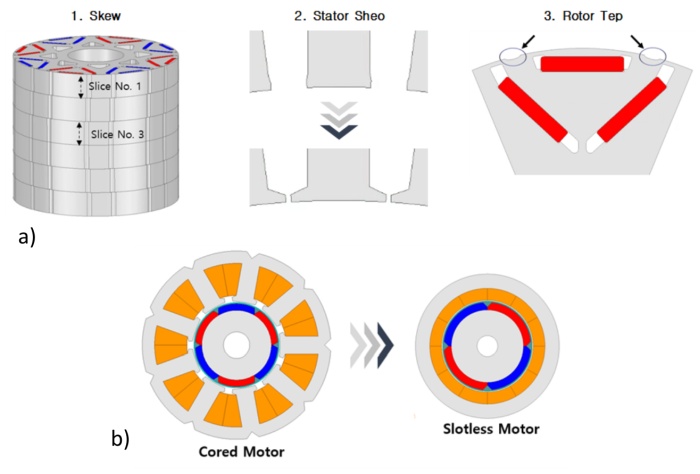
Fig. 1 a) Example of improving precision by changing the shape of the motor. b) Example of precision improvement using slotless motors.
Acknowledgements
This study was supported by the Ministry of Trade, Industry, and Energy (MOTIE) and Korea Evaluation Institute of Industrial Technology (KEIT) of the Republic of Korea under Grant 20023875.
References
[1] K.-D. Lee, J. Lee, and H.-W. Lee, “Inductance Calculation of Flux Concentrating Permanent Magnet Motor through Nonlinear Magnetic Equivalent Circuit,” IEEE Transactions on Magnetics, vol. 51, no. 11. Institute of Electrical and Electronics Engineers (IEEE), pp. 1–4, Nov. 2015. doi: 10.1109/tmag.2015.2438000.
Speaker: Jae-Kwang Lee (Korea Electronics Technology Institute) -
16:00
A Study on the Method to improve Performance through Variable Stopping Power of Permanent Magnet Hybrid Electronic Brakes 2h
In the case of the permanent magnet electronic brake that will be discussed in this paper, a permanent magnet is placed at the bottom of the stator and a winding is placed in the middle of the stator. In the case of attractive force, it is generated by magnetic energy generated by permanent magnets, and current must be applied to the winding to cancel out the stopping force. In the case of a permanent magnet type electronic brake, the maximum stopping force that can be generated is fixed depending on the permanent magnet inserted at the bottom, and the stopping force cannot be changed even if the load conditions vary. In this paper, we studied a method for outputting a permanent magnet type electronic brake. Two methods were proposed to vary stopping power. The first method is to use an Alico 9 magnet with low coercive force and utilize the magnetization and demagnetization phenomenon according to load conditions to utilize stopping power. The second method is to secure additional stopping power by improving the stator and rotor structures to generate iron loss at the moment stopping power is needed. To verify the validity of this study, a prototype of a permanent magnet brake was manufactured and a dynamo test was conducted.

Fig. 1 a) Permanent magnet electronic brake design process. b) Attractive-force analysis using 3D FEA.
Acknowledgements
This study was supported by the Ministry of Trade, Industry, and Energy (MOTIE) and Korea Evaluation Institute of Industrial Technology (KEIT) of the Republic of Korea under Grant 20023875.
References
[1] K.-D. Lee, J. Lee, and H.-W. Lee, “Inductance Calculation of Flux Concentrating Permanent Magnet Motor through Nonlinear Magnetic Equivalent Circuit,” IEEE Transactions on Magnetics, vol. 51, no. 11. Institute of Electrical and Electronics Engineers (IEEE), pp. 1–4, Nov. 2015. doi: 10.1109/tmag.2015.2438000.
Speaker: Jae-Kwang Lee (Korea Electronics Technology Institute) -
16:00
Domain Wall Imaging in Rapidly Solidified Amorphous Submicronic Wires 2h
Rapidly solidified amorphous submicronic glass-coated wires with diameters between 100 and 950 nm, featuring either high or nearly zero magnetostriction, present a bistable magnetic behavior [1], which relies on the propagation of a single magnetic domain wall at velocities that differ considerably in wires with high magnetostriction as compared to those with nearly zero magnetostriction.
Here, we report on the Lorentz microscopy investigation of magnetic domain walls in rapidly solidified submicronic Fe$_{77.5}$Si$_{7.5}$B$_{15}$ and (Co$_{0.94}$Fe$_{0.06}$)$_{72.5}$Si$_{12.5}$B$_{15}$ amorphous wires with high and nearly zero magnetostriction, respectively. Imaging has been performed using a Libra 200 MC Carl Zeiss ultra-high-resolution microscope in Fresnel configuration. Domain wall structures have been observed under an applied field with various amplitudes and directions. Lorentz microscopy data has been associated with hysteresis loop and domain wall velocity measurements for a comprehensive investigation.
Figure 1 shows a domain wall image observed in a nearly zero magnetostrictive sample having 900 nm in diameter, in the absence of an applied field. The domain wall structure does not change with different values of the applied field. Moreover, tilting a field of 900 Oe at small angles with respect to the direction perpendicular to the lamella, does not alter the vortex structure.
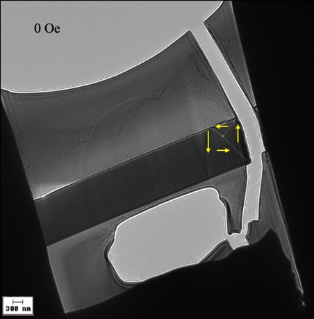
Fig. 1 Lorentz microscopy image of a domain wall in a (Co$_{0.94}$Fe$_{0.06}$)$_{72.5}$Si$_{12.5}$B$_{15}$ submicronic amorphous wire with 900 nm in diameter, with no applied magnetic field.
In case of an Fe$_{77.5}$Si$_{7.5}$B$_{15}$ amorphous submicronic wire with high magnetostriction, having the same diameter (900 nm), the vortex domain wall displays an elongation that increases with the value of the applied field. Tilting the field at small angles has the same effect.
The differences in hysteresis loop parameters and in domain wall velocities displayed by the two types of submicronic amorphous wires can be linked to the differences in their domain wall structures. The results are essential towards fully understanding the magnetic behavior of nearly zero and highly magnetostrictive submicronic amorphous samples.
Acknowledgements
Financial support from the MCID Nucleu Program (PN 23 11 01 01 - contract 18N/2023) is highly acknowledged.
References
[1] S. Corodeanu, C. Hlenschi, C. Rotărescu, H. Chiriac, N. Lupu, and T.-A. Óvári, “Structural relaxation in metastable magnetic submicronic wires,” Journal of Alloys and Compounds, vol. 905, 164260, June 2022. doi: 10.1016/ j.jallcom.2022.164260.
Speaker: Dr Tibor-Adrian Óvári (National Institute of Research and Development for Technical Physics, Iasi, Romania) -
16:00
Eddy Current Testing with TMR Probes for Enhanced Quality Control of Arc Stud Welds 2h
In the automotive industry, ensuring the highest quality of welded components is vital for safety and meeting end-user expectations. Current quality control (QC) practices in welding operations primarily rely on mechanical inspection and reactive procedures. To enhance QC efficiency and anticipate quality issues without destructive testing, it is necessary to apply non-destructive testing (NDT) techniques.
This paper explores the application of Eddy Current Testing (ECT), an NDT technique to QC arc stud welding, a process used to join screws/studs to metal plates. This process might create several defects like weld voids, cracks, and porosity [1] which can be detected earlier. ECT, a contactless electromagnetic technique induces and measures electrical currents within conductive materials [2]. Variations in conductivity, often caused by defects, are detected through changes in the induced currents. ECT capability at identifying surface and near-surface defects that escape visual inspection, makes it a valuable tool for comprehensive welding QC.
This work uses a magneto-resistive (MR) differential-based eddy current probe, offering superior spatial resolution, sensitivity, and bandwidth compared to conventional inductive probes [3], [4]. Employing the differential heterodyne technique, the aim is to optimize the magnetic field response's relative variation while minimizing the impact of inductive coupling on the measured signal [5]. The detection employs two identical MR sensors with a 1 mm pitch, each featuring an array of 26 magnetic tunnel junctions (MTJs) in series, with dimensions of 100$\times$100 $\mu m^2$. A scan image of a weld alongside the photograph (Fig. 1) highlights the capability to accurately identify the weld region under specific parameters: 0.5 $_{App}$ stimulation line at 2 kHz and a sensor bias of 300 mVpp at 25 kHz.

Fig. 1 Weld photograph (a) and magnitude and phase scan (b).
This paper focuses on understanding the scans conducted over real automotive welds. Starting with the analysis of identical plates containing machined buried defects at different distances from the scan surface, ranging from 0.1 up to 0.4 mm. The aim is to comprehend the probe's response to these defects, thereby enabling the recognition in actual welds. Throughout this process, COMSOL models were fine-tuned to aid in and validate weld imaging. This research contributes to advancements in NDT by demonstrating the effectiveness of an ECT probe design for welding QC.
Acknowledgements
Project GrenAuto Mobilising Agendas for Business Innovation, funded by the Recovery and Resilience Plan and by European Funds NextGeneration EU.
References
[1] “Welding - Arc stud welding of metallic materials (ISO 14555:2017),” 2017.
[2] J. García-Martín, J. Gómez-Gil, and E. Vázquez-Sánchez, “Non-destructive techniques based on eddy current testing,” Sensors, vol. 11, no. 3. pp. 2525–2565, Mar. 2011. doi: 10.3390/s110302525.
[3] M. Pelkner, R. Pohl, T. Erthner, R. Stegemann, M. Kreutzbruck, and N. Sergeeva-Chollet, "Eddy Current Testing with High-spatial Resolution Probes using MR Arrays as Receiver," presented at the 7th International Symposium on NDT in Aerospace, 16-18 Nov. 2015, Bremen, Germany. [Online]. Available: https://www.ndt.net/?id=18969.
[4] B. Ribes Sáez, N. Sergeeva-Chollet, F. Cardoso, L. Bragado, C. Fermon, S. Cardoso, P. Freitas, M. Piedade, and L. Rosado, "Results of MR based ET probes for buried flaw detection over different metallic materials," presented at the 11th European Conference on Non-Destructive Testing (ECNDT 2014), Prague, Oct 6-11, 2014. [Online]. Available: https://www.ndt.net/?id=16654.
[5] L. S. Rosado, F. A. Cardoso, S. Cardoso, P. M. Ramos, P. P. Freitas, and M. Piedade, “Eddy currents testing probe with magneto-resistive sensors and differential measurement,” Sens Actuators A Phys, vol. 212, pp. 58–67, Jun. 2014, doi: 10.1016/j.sna.2014.03.021.Speaker: Susana Cardoso (INESC MN, Instituto Superior Técnico) -
16:00
Experimental Study of Magnetic Nanoparticles for Magnetic Separation DNA/RNA 2h
Magnetic nanoparticles have been the subject of much research with their unique properties such as size in the nanoscale and the existence of high magnetic moment which bring a wide range of their applications. It is their ability to respond to an external magnetic field that enables their motion control. Their application in biomedicine is interesting, where they show promise as drug carriers, as heat sources in magnetic particle hyperthermia for cancer therapy, in MRI imaging techniques and also in separation techniques using an external magnetic field [1].
At the same time, separation techniques are notoriously time-consuming and technically demanding, which often brings negative impacts in the process of diagnosis and therapy of various viral and bacterial diseases. Also, the specificity of various viral and bacterial diseases limits the possibilities of using conventional separation techniques due to the low concentration of the captured target substances. One of the new approaches in this field is magnetic separation using magnetic nanoparticles [2].
The thesis deals with the application of magnetic nanoparticles as nucleic acid separation reagents in RT-PCR assays. One of the main objectives of the work is to design such nanoparticle systems that, by their specific properties such as shape, magnetic moment magnitude, or the presence of ligand on the nanoparticle surface, would accelerate the separation of nucleic acids and increase the amount of bound genetic material during RT-PCR testing. The potential of magnetic nanoparticles to bind DNA/RNA molecules is investigated on SiO$_2$-coated Fe$_3$O$_4$-type nanoparticles with a specific organic ligand on the surface. Also, the work is devoted to the preparation of star-shaped nanoparticles, or cubic nanoparticles which by their specific shape can bind DNA/RNA molecules more efficiently compared to spherical nanoparticles. Our synthesized nanoparticles have been investigated for their ability to bind nucleic acids. This type of nanoparticles is also characterized in terms of structure, morphology and magnetic properties.
Speaker: Michael Barutiak (Univerzita Pavla Jozefa Šafárika v Košiciach, Prírodovedecká fakulta, Ústav fyzikálnych vied, Katedra fyziky kondenzovaných látok) -
16:00
Fabrication and Characterization of Heusler Alloy Thin Films and Nanowires 2h
Heusler alloys are suitable materials for sensors and actuators [1]. The current challenge in the utilization of shape memory Heusler alloys remains in their downsizing [2]. In this work we present such materials in the form of thin films and nanowires, which were fabricated using electrodeposition. This approach presents a scalable method for fabrication of shape memory materials, which can be used for sensing and actuation in the nanoscale.
Electrodeposition of Ni$_2$FeGa thin films and nanowires, which show a shape memory behavior due to a martensitic transformation capability, was followed by a complete substitution of the Ga atom in their composition by Tl. The Ga substitution resulted in off-stoichiometric Ni-Fe-Tl nanowires with a phase transition at the temperature of $\approx$ 350 K, confirmed by structural and magnetic analysis.
First-order reversal curve analysis of an array of the Ni-Fe-Tl nanowires reveals a change in their magnetization process before and after the phase transition, enabling contactless sensing mechanism of the nanowires’ magnetostructural response [3,4]. Moreover, the phase transition-driven magnetization variations make the nanowires suitable for hyperthermic application. Wide temperature hysteresis of the nanowires’ phase transition offers a possibility to gradually heat the nanowires under an alternating magnetic field. The heating process can be automatically interrupted after the nanowires transform into the high-temperature phase due to a > 70$\%$ change in the hysteresis losses between the magnetically soft austenite and magnetically hard martensitic phase.
Acknowledgements
The authors would like to thank the following projects for the financial support of the presented research: The projects APVV-16-0079 and APVV-20-0205 of the Slovak Research and Development Agency, and projects VEGA 1/0053/19, VEGA 1/0180/23, as well as the project VVGS-2022-2408 of the UPJS.
References
[1] L. Frolova et al., “Smart Shape Memory Actuator Based on Monocrystalline Ni2FeGa Glass-Coated Microwire,” IEEE Trans Magn, vol. 54, no. 11, pp. 1–5, Nov. 2018, doi: 10.1109/TMAG.2018.2848670.
[2] M. Varga et al., “FORC and TFORC analysis of electrodeposited magnetic shape memory nanowires array,” J Alloys Compd, vol. 897, p. 163211, Mar. 2022, doi: 10.1016/j.jallcom.2021.163211.
[3] C. I. Dobrotǎ and A. Stancu, “What does a first-order reversal curve diagram really mean? A study case: Array of ferromagnetic nanowires,” J Appl Phys, vol. 113, no. 4, p. 043928, Jan. 2013, doi: 10.1063/1.4789613.
[4] M. R. Zamani Kouhpanji, A. Ghoreyshi, P. B. Visscher, and B. J. H. Stadler, “Facile decoding of quantitative signatures from magnetic nanowire arrays,” Sci Rep, vol. 10, no. 1, p. 15482, Sep. 2020, doi: 10.1038/s41598-020-72094-4.Speaker: Michal Varga (Faculty of Materials, Metallurgy and Recycling, Technical University of Kosice, Letna 9, 040 01 Kosice, Slovak Republic) -
16:00
FMR Study of ZnFe2O4 Thin Films in varied Growth Environments 2h
This study investigates the magnetic properties of ZnFe$_2$O$_4$ thin films, emphasizing the impact of growth conditions on their ferromagnetic resonance (FMR) spectra. Utilizing X-ray diffraction (XRD) and Raman spectroscopy, the films were analysed under different substrates, growth temperatures, and gas ambient. Key findings highlight variations in change in FMR line width, saturation magnetization, suggesting a significant influence of growth environments on magnetic behaviour. FMR spectroscopy study has been carried out at room temperature using a broad-band FMR set-up, with an excitation frequency varying from 3 to 18 GHz. For clarity, we have chosen to present data for specific GHz ranges. From the measurements obtained, we calculated the line width ($\Delta H$) and resonance field ($H_r$). It is important to highlight that the FMR signal exhibited greater strength in the argon environment in comparison with the oxygen environment. FMR spectroscopy provides valuable insights into crucial aspects like magnetic anisotropy, magnetic damping, and exchange interactions [1]. These insights are crucial for the development and optimization of spintronic devices [2], providing a deeper understanding of material properties under diverse conditions.
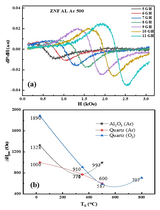
Fig.1 a) FMR spectra of Zinc-ferrite films deposited on Al$_2$O$_3$ substrate at 500 $^\circ$C in an argon environment, and b) The parallel line width ($\Delta H_{par}$) plotted against various $T_S$ (substrate temperature) and substrate types.
References
[1] S. M. Yakout, “Spintronics: Future Technology for New Data Storage and Communication Devices,” Journal of Superconductivity and Novel Magnetism, vol. 33, no. 9. Springer Science and Business Media LLC, pp. 2557–2580, May 31, 2020. doi: 10.1007/s10948-020-05545-8.
[2] Y. Wang, R. Ramaswamy, and H. Yang, “FMR-related phenomena in spintronic devices,” Journal of Physics D: Applied Physics, vol. 51, no. 27. IOP Publishing, p. 273002, Jun. 20, 2018. doi: 10.1088/1361-6463/aac7b5.Speaker: Murtaza Bohra (Mahindra University, India) -
16:00
Glass-coated Ni50Mn37Sb13 Microwires: Synthesis and Magneto-Structural Characterization 2h
Magnetic Heusler alloys, which undergo a martensitic-like structural transition, display interesting functional properties. Regarding the synthesis of these alloys, most of the work conducted up to now has focused on bulk and ribbon samples prepared using conventional melting and melt-spinning techniques. This work reports the microstructure, structural, magnetic, and magnetocaloric characteristics of polycrystalline glass-coated Ni$_{50}$Mn$_{37}$Sb$_{13}$ microwires obtained by the Taylor-Ulitovsky technique. The results are compared with those obtained for a bulk alloy of the same composition. The microwires exhibited a remarkably uniform diameter, averaging around 200 microns. Elemental chemical composition analyses reveal slight deviations in the Mn and Sb content from the nominal values. At room temperature, austenite shows an L2$_1$-type cubic crystal structure (space group Fm-3m) and undergoes a second-order magnetic phase transition with a Curie temperature ($T_C^A$) of 332 K. The thermomagnetic curve measured under a field of 5 mT in the temperature range from 150 K to 400 K shows the occurrence of a broad first-order martensitic-like phase transition at a temperature of around 233 K. One notable room temperature magnetic characteristic of these samples is their ability to achieve saturation magnetization at a low magnetic field strength of around 0.15 T. For a magnetic field change of 2 T, the produced microwires show a maximum magnetic entropy change $|\Delta SM|_{max}$ of 1.2 Jkg$^{-1}$K$^{-1}$ at the second-order transition of austenite.
Acknowledgements
Work supported by Laboratorio Nacional de Investigaciones en Nanociencias y Nanotecnología (LINAN, IPICyT), CONAHCYT, Mexico (research project CF-2023-I-2143), The Slovak Grant Agency APVV-160079 grant and VEGA 1/0180/23. M. López-Cruz thanks CONAHCYT and SAIA for supporting his Ph.D. studies at IPICyT (scholarship 831827) and his stay at UPJS, Slovakia. The technical support received from Dr. I.G. Becerril Juárez is acknowledged.
Speaker: Michal Varga (Faculty of Materials, Metallurgy and Recycling, Technical University of Kosice, Letna 9, 040 01 Kosice, Slovak Republic) -
16:00
High Frequency of Symmetric/Asymmetric Ferromagnetic Coupled Bilayers 2h
Nowadays, we are immersed in a digital society where information is continually transferred between different devices, forcing us to look for new alternatives that allow the faster transfer of information with the lowest possible energy consumption. Magnetic thin films have been successfully used but their related natural resonance frequency is restricted to the range of a few GHz, and it should be increased to allow for current technological needs [1]. In 2016, Li et al. [2] proved that coupled ferromagnetic bilayers can present higher ferromagnetic resonances, the acoustic and optic modes, as compared to single thin films.
Here, the static and dynamic magnetic responses of symmetric and asymmetric multilayer bimagnetic systems of different non-magnetic spacer thickness have been studied. The symmetric system is composed of Fe(10nm)/Al (0-2nm)/Fe(10nm), and the antisymmetric one of Co(10nm)/Cu(0-8nm)/CoFeB(10nm) [3]. We have observed both the acoustic and optic modes and it is demonstrated that the resonance frequency of the optic mode is very sensitive to the interlayer coupling constant that depends on the geometrical and compositional nature of layers. Particularly, high resonance frequencies can be achieved (over 25 GHz) for Co/CoFeB bilayers with interlayer exchange coupling $J_{eff}$ = (2.7 $\pm$ 0.8) erg/cm$^2$.
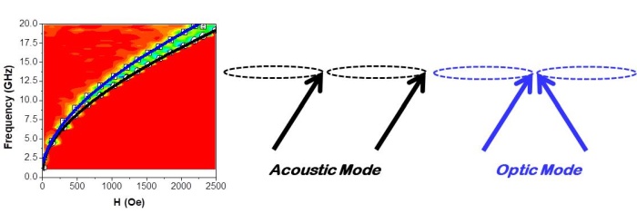
Fig. 1 VNA-FMR spectra of Co(10nm)/Cu(3nm)/CoFeB(10nm) trilayer where black and blue lines correspond to the acoustic and optic modes, respectively. Diagrams of both modes.
Acknowledgements
Authors acknowledge financial support from Projects CNS2022-135949 and PID2022-137567NB-C21 by the Spanish Ministry of Science and Innovation, Project FONDECYT/REGULAR 1201102 by ANID, and Projects UIDP/04968/2020 and 2022.03564.PTDC by FCT.
References
[1] K. David and H. Berndt, “6G Vision and Requirements: Is There Any Need for Beyond 5G?,” IEEE Vehicular Technology Magazine, vol. 13, no. 3. Institute of Electrical and Electronics Engineers (IEEE), pp. 72–80, Sep. 2018. doi: 10.1109/mvt.2018.2848498.
[2] S. Li et al., “Tunable Optical Mode Ferromagnetic Resonance in FeCoB/Ru/FeCoB Synthetic Antiferromagnetic Trilayers under Uniaxial Magnetic Anisotropy,” Advanced Functional Materials, vol. 26, no. 21. Wiley, pp. 3738–3744, Apr. 13, 2016. doi: 10.1002/adfm.201600122.
[3] Z. Wei et al., “Static and dynamical behaviour of magnetically coupled Co/Cu/CoFeB trilayers,” Journal of Magnetism and Magnetic Materials, vol. 589. Elsevier BV, p. 171584, Jan. 2024. doi: 10.1016/j.jmmm.2023.171584.Speaker: Rafael Perez del Real (Institute of Materials Science of Madrid, ICMM-CSIC) -
16:00
Inductance Calculation of Small Spoke Motor using Equivalent Circuit 2h
The inductance of an IPM motor is an important factor in determining the performance of the motor.In particular, spoke type motors use salient pole ratios to utilize reluctance torque, so accurate inductance calculation is an important technique. Many papers have previously been published on inductance calculation methods [1-2]. Recently, with the development of computers, the method of calculating inductance using FEM is widely used. However, the process has the disadvantage of being complicated and time-consuming. Of course, when using FEM, the iron core saturation phenomenon can be calculated with high precision, so the inductance calculation result has the advantage of being highly accurate.
Figure 1 shows the inductance calculated by FEM. $L_{d}$ and $L_{q}$ represent the inductance of each $d$-axis and $q$-axis. Inductance varies depending on the magnitude and phase angle of the current. When calculating with an equivalent circuit, a complicated process is required to accurately calculate the magnetic saturation phenomenon.
In this paper, the inductance was calculated using the magnetic equivalent circuit method and the results were compared with the FEM calculation method. A method of increasing accuracy was applied by applying the iron core saturation nonlinear function and the permanent magnet demagnetization function. A comparison of the analysis results will be presented in the full paper.
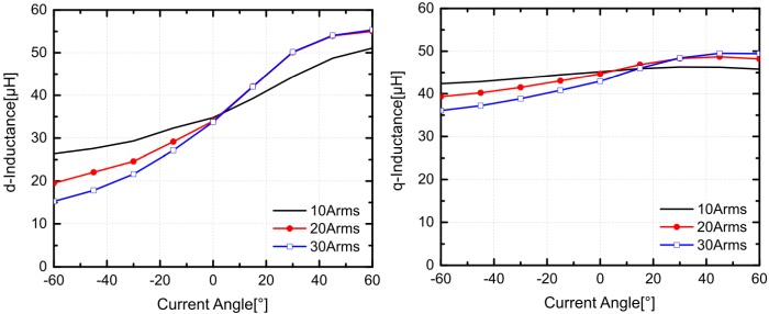
Fig. 1 Inductance calculation results according to current and phase angle using FEM analysis.
Acknowledgements
This work was supported by the Technology Innovation Program (No. 20023928) funded By the Ministry of Trade, Industry & Energy (MOTIE, Korea).
References
[1] Ki-Doek Lee, Ju Lee, and Hyung-Woo Lee, “ Inductance Calculation of Flux Concentrating Permanent Magnet Motor through Nonlinear Magnetic Equivalent Circuit,” IEEE Transactions on Magnetics, vol. 51, no. 11, Institute of Electrical and Electronics Engineers (IEEE), Article Sequence Number: 8204304, November 2015. doi: 10.1109/TMAG.2015.2438000.
[2] Baichuan Xu, Kai Yang, Senior Member, IEEE, Feng Jiang, Songjun Sun, and Yixiao Luo, “ D-Q Axis Inductance Analytical Calculation for Fractional-Slot Distributed Winding IPM Motor Based on Big-Small Pole Space Method,” IEEE Transactions on Industrial Electronics, vol. 71, no. 2 Institute of Electrical and Electronics Engineers (IEEE), pp.1341-1354, February 2024. doi: 10.1109/TIE.2023.3247779.Speaker: Jeong Jong Lee (Korea Electronics Technology Institute) -
16:00
Influence of Chemical Composition Change on Ni2NbSn – Heusler Ferromagnetic Superconductor 2h
Heusler alloys are a unique class of materials which enable the option to change their physical properties by simple adjustment of the alloy's chemical composition. It was shown in different studies, that changes in chemical composition can lead to tuning of the observed phenomenon, and its enhancement. Well-known Heusler ferromagnetic superconductor Ni$_2$NbSn has a critical temperature of 3 K and Curie temperature of around 13 K. Mainly the value of critical temperature makes the material difficult to study and does not support its practical application.
In the presented work, the influence of chemical doping of Ni$_2$NbSn using Ga, Ge, and Sb elements was investigated. The most crucial parameters were evaluated, such as superconducting transition temperature, and also Curie temperature. The chemical tuning of the mother alloy was performed with 1$\%$ and 2$\%$ doping. It was found that doping may in some cases suppress the superconducting or ferromagnetic properties in the material, but on the other hand, favourable enhancement of superconducting temperature has been observed for 1$\%$ Sb doping, up to 6.42 K. The resistance measurements revealed the background of the coexistence of ferromagnetism and superconductivity can be different than in the case of other chemical doping.
Acknowledgements
This work was supported by the projects APVV-16-0079, Slovak VEGA grant. No. 1/0180/23, 1/0404/21, 2/0058/20. University Science Park TECHNICOM for Innovation Applications Supported by Knowledge Technology– II- Phase, ITMS: 313011D232., supported by the Research \& Development Operational Programme funded by the ERDF.
References
[1] S. Nalevanko, J. Kačmarčík, L. Galdun, et. al., “Ni$_2$NbSn Heusler ferromagnetic superconductor: Magneto-structural and transport characterisation,” Intermetallics, vol. 167, no. 108231, Feb. 2024. doi: 10.1016/j.intermet.2024.108231.
[2] A. Reigle, K. Mason, J. Slattery, et. al., “Superconducting properties of in doped ZrNi$_2$Ga$_{1−x}$In$_x$, ” Solid State Commun, vol. 291, pp. 28–31, Jan 2019. doi: 10.1016/j.ssc.2019.01.015.
Speaker: Samuel Nalevanko (CPM-TIP, UPJS) -
16:00
Influence of Chemical Doping on Magnetic Characteristic of ErMn$_{1-x}$Fe$_{x}$O$_3$ Multiferroic System 2h
ErMnO$_3$ is the improper multiferroic compound with ferroelectric ordering temperature of $T_c$ = 835 K, but with the magnetism presented only below Neel temperature of $T_N$ = 81 K [1]. This temperature is too low for the application purposes. On the other hand, ErFeO$_3$ system does not exhibit the ferroelectric ordering, but it orders magnetically into antiferromagnetic structure below $T_N$ = 643 K [2]. In order to have a multiferroic material with high application potential, one has to ensure that both, ferroelectric and magnetic orderings occur at temperature higher than room temperature. Extrapolating from parent ErMnO$_3$ and ErFeO$_3$ compound we have expected that such a material can be found in the ErMn$_{1-x}$Fe$_{x}$O$_3$ substitutional system. For these reasons we have prepared the Fe-doped ErMnO$_3$ materials and examined their magnetic properties.
Nanopowders of ErMn$_{1-x}$Fe$_{x}$O$_3$ ($0 \leq x \leq 1$) were prepared by nitrate glycine method. The compounds crystallize in hexagonal structure for $0 \leq x \leq 0.2$ and in orthorhombic structure for $0.5 \leq x \leq 1$. The co-existence of both, hexagonal and orthorhombic phase was observed in the concentration range $0.2 < x < 0.5$. Since the multiferroicity was observed in the hexagonal phase, the magnetism was investigated for $0 \leq x \leq 0.2$ compounds. It was found that all compounds order magnetically at low temperatures, exhibiting hysteresis loops [$M(B)$] at 2 K with very low coercivity field of 0.06 T; 0.04 T and 0.035 T and very low remnant magnetization of 0.18 $\mu_{B}/\mathrm{f.u.}$; 0.1 $\mu_{B}/\mathrm{f.u.}$ and 0.08 $\mu_{B}/\mathrm{f.u.}$ for $x$ = 0; 0.1 and 0.2 composition. The hysteresis loops do not saturate at magnetic field of $\mu_0 H$ = 5 T. No visible anomalies can be observed on $dTM(T)/dT$ curves. Anomalies in $d^2TM(T)/dT^2$ which we associate with magnetic phase transition, are located at 76.9 K, 79.7 K and 82.4 K. All samples are paramagnetic at 150 K as proven from $M(B)$ loops at this temperature and the Curie-Weiss fit of the high temperature $M(T)$ curves indicate that the anomaly in $d^2TM(T)/dT^2$ is connected with paramagnetic to weak ferromagnetic / canted antiferromagnetic phase transition.
Concluding, Neel temperature increases with iron doping, but it does not reach the room temperature within the concentration range of stable hexagonal crystal structure. The magnetic ordering phase transition is of higher order. Additional consequences and effects of the Mn-Fe doping in this system will be discussed within the conference contribution.
Acknowledgements
This research has been supported by VEGA Project No. 2/0011/22.
References
[1] F. Yen et al., “Magnetic phase diagrams of multiferroic hexagonal RMnO3 (R = Er, Yb, Tm, and Ho),” Journal of Materials Research, vol. 22, no. 8. Springer Science and Business Media LLC, pp. 2163–2173, Aug. 2007. doi: 10.1557/jmr.2007.0271.
[2] D. Treves, “Studies on Orthoferrites at the Weizmann Institute of Science,” Journal of Applied Physics, vol. 36, no. 3. AIP Publishing, pp. 1033–1039, Mar. 01, 1965. doi: 10.1063/1.1714088.Speaker: Dr Matúš Mihalik (Institute of Experimental Physics, Slovak Academy of Science) -
16:00
Low-frequency Soft Magnetic Composites produced from BN and Al2O3 Mechanocoated NiFeMo Ferromagnetic Alloy 2h
This study examined the effect of the ratio and type of insulation used on the magnetic performance of NiFeMo-based SMCs. We prepared five samples: pure NiFeMo “S1”, two composites with BN-based insulation (1.16 vol$\%$ “S2” and 5 vol$\%$ “S3”), and two Al$_2$O$_3$ (1.16 vol$\%$ “S4” and 5 vol$\%$ “S5”). The ferromagnetic part and the insulator were mixed in 30 ml vials and placed in a custom-prepared setup inside a planetary ball mill at a rotation speed of 500 rpm for 15 minutes. Then, they were compacted in Ar atmosphere at 400 $^\circ$C and 700 MPa for 5 mins and left to cool down.
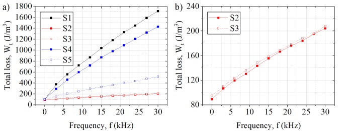
Fig. 1 Total loss of (a) all samples and (b) samples S2 and S3 measured in the DC-30 kHz frequency range.
Resistivity $\rho_R$ was measured using the contactless method. For S1 $\rho_R$ is 15 $\mathrm{\mu\Omega m}$, S2 190 $\mathrm{\mu\Omega m}$, S3 480 $\mathrm{\mu\Omega m}$, S4 18 $\mathrm{\mu\Omega m}$ and S5 54 $\mathrm{\mu\Omega m}$. Maximum relative permeability $\mu_{max}$ and the real part of complex permeability peak $\mu_r$ reduced with the increased insulation percent, and for sample S1, $\mu_{max}$ and $\mu_r$ have the highest values of around 280 and 120. BN-insulated S2 and S3 have large drops, $\mu_{max}$ are around 190 and 150, and $\mu_r$ 110 and 90, respectively. Al$_2$O$_3$-coated S4 has the lowest drops related to S1, $\mu_{max}$ is 240, and $\mu_r$ is 105; $\mu_{max}$ of sample S5 is around 160, and $\mu_r$ is around 90.
Relaxation frequency $f_r$ tended to grow with the amount of the insulation. In the compact S1, $f_r$ of 6.4 kHz is already high for a pure ferromagnet. BN insulation increased it to around 260 kHz in S2 and 400 kHz in S3. The $f_r$ of Al$_2$O$_3$ in S4 is around 60 kHz and in S5 around 80 kHz. Magnetic loss (Fig. 1), measured in the DC-30 kHz frequency range, confirmed that effect. Hysteresis loss $W_h$ is around 90 J/m$^3$ in all samples. Total energy loss $W_t$ at 30 kHz revealed the superiority of BN-coated powder-based SMCs. The $W_t$ of S1 has a value of around 1700 J/m$^3$; in both S2 and S3, it is around 200 J/m$^3$, and their growth is similar. A low amount of Al$_2$O$_3$ in S4 appears less effective, as its $W_t$ value is around 1430 J/m$^3$; however, 5 vol$\%$ of Al$_2$O$_3$ reduces losses to a greater extent, and $W_t$ is around 510 J/m$^3$.
Acknowledgments
This work was realized within the frame of the project “FUCO” financed by the Slovak Research and Development Agency under the contract APVV-20-0072; the Scientific Grant Agency of Ministry of Education of Slovak Republic and Slovak Academy of Sciences (projects VEGA 1/0016/24 and 1/0132/24) and the Internal Scientific Grant of the Faculty of Science, P.J. Šafárik University in Košice (project VVGS-2023-2528).
Speaker: Robert Maciaszek (Pavol Jozef Šafárik University in Košice) -
16:00
Magnetic Analysis of Fe-based Nanoparticles for Biomedical Applications 2h
Iron nanoparticles have emerged as a promising frontier in the realm of nanomedicine, offering unprecedented potential for revolutionizing diagnostics, imaging, targeting, drug delivery, and therapy [1]. Their unique physicochemical properties, such as high surface area-to-volume ratio, tunable magnetic properties, and biocompatibility, make them ideal candidates for various biomedical applications [2].
We have prepared the nanoparticle system consisting of Fe$_3$O$_4$ magnetic core coated with a silica SiO$_2$ shell with a size of approximately 10 nm. Such system was detailly analyzed in terms of magnetic properties. In Fig. 1 the magnetization measurement in ZFC/FC mode at applied external magnetic field of 100 Oe is presented.
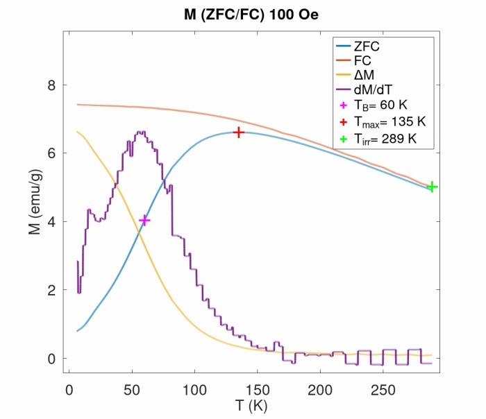
Fig. 1 Magnetic measurements in ZFC/FC mode at applied external magnetic field of 100 Oe.
Magnetic properties of the system have been examined in AC and DC conditions. Isothermal magnetization data taken at temperature span 5-300 K confirmed superparamagnetic behavior of the system above 50 K. The series of ZFC-FC measurements under various applied DC fields revealed field dependence of blocking temperature and signatures of interparticle interactions in the system. The strength of the interactions has been determined by means of various methods. The construction of Henkel plot points to the dipole-dipole origin of the magnetic interactions. Neel-Arrhenius, Vogel-Fulcher and the Critical slowing down models have been applied to the collected AC magnetic susceptibility vs temperature data. The analysis reconfirmed the presence of intermediate/strong interparticle interactions in accordance with the results obtained from DC data.
Acknowledgements
This work was supported by the Slovak Research and Development Agency under the contract APVV-20-0512 and by the Operational Programme Integrated Infrastructure, project “NANOVIR”, ITMS:313011AUW7, co-funded by ERDF.
References
[1] P. Farinha, J. M. P. Coelho, C. P. Reis, and M. M. Gaspar, “A Comprehensive Updated Review on Magnetic Nanoparticles in Diagnostics,” Nanomaterials, vol. 11, no. 12. MDPI AG, p. 3432, Dec. 17, 2021. doi: 10.3390/nano11123432.
[2] N. Elahi and M. Rizwan, “Progress and prospects of magnetic iron oxide nanoparticles in biomedical applications: A review,” Artificial Organs, vol. 45, no. 11. Wiley, pp. 1272–1299, Jul. 09, 2021. doi: 10.1111/aor.14027.Speaker: Dr Jaroslava Szűcsová (UPJŠ Košice) -
16:00
Magnetic Properties and Magnetization Processes in the SMCs Influenced by the Mechanofusion Parameters 2h
Soft magnetic composites (SMCs) are in general ferromagnetic powder particles surrounded by electroinsulating layer [1]. In this work we examined magnetic properties and magnetization processes in Fe-based soft magnetic composites with Al$_2$O$_3$ electroinsulating layer created by mechanofusion process. Mechanofusion (also called dry coating) is process which attaches small particles (Al$_2$O$_3$ powder, 1-40 $\mu$m) on larger particles (Fe powder, 125-200 $\mu$m) without the use of any binders and solvents [2]. Two series of four ring samples with rectangular cross-section were created, based on mechanofusion time and the amount of the Al$_2$O$_3$ powder in powder mixture. The names of the samples were chosen as follows: the letter indicates the time of mechanofusion (S means short (15 minutes) and L means long (30 minutes)) and the number indicates the weight percentage of Al$_2$O$_3$ used in mixture with Fe powder. We examined electrical resistivity, coercivity, complex permeability and AC and DC losses. The DC loss separation according to Landgraf´s approach was executed [3].
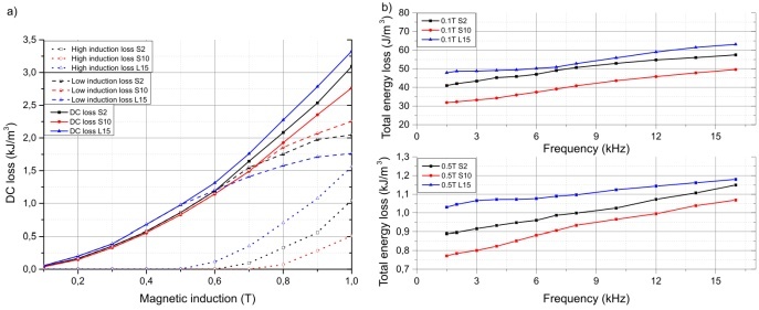
Fig. 1 DC loss and DC loss separation according to Landgraf´s approach (a) and AC loss (b).
We found that, the optimal Al$_2$O$_3$ content for shorter mechanofusion process duration is around 5-10 $\%$, because of the lowest loss and the highest permeability. Longer mechanofusion process with increasing of Al$_2$O$_3$ content leads to deterioration of the magnetic properties of SMCs.
Acknowledgements
This work was realized within the frame of the project “FUCO” financed by Slovak Research and Development Agency under the contract APVV-20-0072 and by Scientific Grant Agency of Ministry of Education of Slovak Republic and Slovak Academy of Sciences – projects VEGA 1/0016/24 and 1/0132/24.
References
[1] H. Shokrollahi and K. Janghorban, “Soft magnetic composite materials (SMCs),” Journal of Materials Processing Technology, vol. 189, no. 1–3. Elsevier BV, pp. 1–12, Jul. 2007. doi: 10.1016/j.jmatprotec.2007.02.034.
[2] F. Jay, V. Gauthier, and S. Dubois, “Iron Particles Coated with Alumina: Synthesis by a Mechanofusion Process and Study of the High‐Temperature Oxidation Resistance,” Journal of the American Ceramic Society, vol. 89, no. 11. Wiley, pp. 3522–3528, Sep. 12, 2006. doi: 10.1111/j.1551-2916.2006.01266.x.
[3] F. J. G. Landgraf, J. C. Teixeira, M. Emura, M. F. de Campos, and C. S. Muranaka, “Separating Components of the Hysteresis Loss of Non-Oriented Electrical Steels,” Materials Science Forum, vol. 302–303. Trans Tech Publications, Ltd., pp. 440–445, Jan. 1999. doi: 10.4028/www.scientific.net/msf.302-303.440.Speaker: Martin Tkáč (UPJŠ) -
16:00
Magnetic Properties of CoFe2O4 Octapods 2h
Octapod-shaped CoFe$_2$O$_4$ nanoparticles represent an interesting and promising material in the field of magnetic properties and their applications. These nanoparticles have a unique octapod-shaped structure and exhibit exceptional magnetic properties that predispose them for use as sensitive detection objects in magnetic devices.
The sensitivity and efficiency of CoFe$_2$O$_4$ nanoparticles as detectors can be greatly enhanced due to the possibility of modifying their shape and structure. This property allows fine-tuning of their magnetic characteristics, which may be prospective, for example, in magnetic particle hyperthermia in the application of alternating magnetic fields.
Moreover, CoFe$_2$O$_4$ nanoparticles will also find applications in biomedical environments, especially as contrast agents in magnetic resonance imaging (MRI). Their ability to be detected by magnetic devices with high sensitivity and precision makes them ideal candidates for improved imaging diagnostic methods and more accurate localization of pathological processes in the human body. Overall, the research and use of CoFe$_2$O$_4$ nanoparticles present an interesting example of synergistic interaction between materials science and biomedicine, which promises to expand their applications in the fields of sensing, diagnostics, and therapeutics.
The octapod CoFe$_2$O$_4$ nanoparticles were prepared via Thermal decomposition of iron(III) acetylacetonate and cobalt(II) acetylacetonate in the presence of sodium oleate and oleic acid. Transmission electron microscopy (TEM) images confirmed that the as-prepared product consists of four-armed star-like cobalt ferrite particles. Prepared nanoparticles had size 15 nm and their saturation magnetisation is around 80 emu/g. As the as-prepared nanoparticles were unsuitable for biomedical applications, we transferred the nanoparticles to aqueous media using the ligand exchange.
References
[1] Y. Eom, M. Abbas, H. Noh, and C. Kim, “Morphology-controlled synthesis of highly crystalline Fe3O4 and CoFe2O4 nanoparticles using a facile thermal decomposition method,” RSC Advances, vol. 6, no. 19. Royal Society of Chemistry (RSC), pp. 15861–15867, 2016. doi: 10.1039/c5ra27649g.
[2] N. Abimathi, H. Harshene, and B. Vidhya, “Synthesis and characterization of CoFe2O4 nanoparticles with its medical application,” Materials Today: Proceedings, vol. 62. Elsevier BV, pp. 2315–2319, 2022. doi: 10.1016/j.matpr.2022.04.101.Speaker: Žaneta Fabriciová -
16:00
Modelling of the Hysteresis Originating from Reversible Magnetization Processes and the Accompanying Energy Losses 2h
In this work, we confirmed that reversible magnetization mechanisms also contribute to the hysteresis of the magnetizing reversal, and are accompanied with an energy loss, which was explained as originating from the frictional effects when local spins rotate. We modelled this hysteresis by calculating the area of the small hysteresis loops obtained by integrating of the reversible relative permeability measured along DC hysteresis loops (Fig. 1). This approach fills the gap, as many models neglect these effects and attribute the whole energy loss to irreversible magnetization, and the mentioned small hysteresis has until now been only commented qualitatively. Here, we quantified the energy dissipation coming from reversible magnetization for different representative Fe-based soft magnetic powder compacted and composite materials, under different magnetizing conditions of a DC magnetization cycle, and we found that different parameters lead to different percent proportions of the particular types of magnetization processes. Further analysis of these results led to a finding confirming theoretical assumption that the reversible rotations of magnetization vector are much more energy consuming than the reversible displacements of domain walls, hence the area of a hysteresis loop of the integrated reversible permeability approximately reflects the reversible magnetization vector rotations percentage within all magnetization processes. Such approach enables to quantify the proportions of reversible magnetization vector rotations solely, because the reversible permeability measurements reflect the portion of all reversible magnetization processes including the reversible domain wall displacements.

Fig. 1 The small hysteresis in reversible magnetization curves (obtained by integration of reversible permeability) observed in Fe-based powder compacted material at maximum induction 0.8 T (left) and 1.2 T (right), compared with DC hysteresis loops.
Acknowledgements
This work was realized within the frame of the project “FUCO” financed by the Slovak Research and Development Agency under the contract APVV-20-0072; and the Scientific Grant Agency of Ministry of Education of Slovak Republic and Slovak Academy of Sciences (project VEGA 1/0132/24).
Speaker: Zuzana Birčáková (Institute of Materials Research, Slovak Academy of Sciences, Watsonova 47, 04001 Košice, Slovakia) -
16:00
Ni2FeGa Shape Memory Microwire for Micro-Actuators 2h
Ni$_2$FeGa shape memory microwire is a potential material for micro-actuators [1]. One of the methods to demonstrate the actuator property of microwire could be provided by the joule heating method [2]. Interestingly, the micro-diameter (r) of shape memory microwire gives high electric resistance (R) wire following the specific electrical resistivity equation.
$R = \rho \frac{L}{\pi r^{2}}$
The higher electric resistance will ensure sufficient heat to induce a phase transformation in the shape memory microwire. Modulation of the electric current in the form of a triangular signal is beneficial for analyzing the phase transformation behavior in the microwire, which can be confirmed by an in-situ diffraction experiment.In this work, a sample with stable phase transformation was obtained from glass-removal and heat-treated shape memory microwire. The heating current profile from the sample with 0.1 Hz triangular signal is presented in Fig. 1. The phase transformation between Martensite Phase and Parent Phase is estimated to be around 15 mA. Further measurements show that the microwire can have a million cycles of stable current for phase transformation and an observable phase transformation profile of up to 10 Hz of the triangular signal.
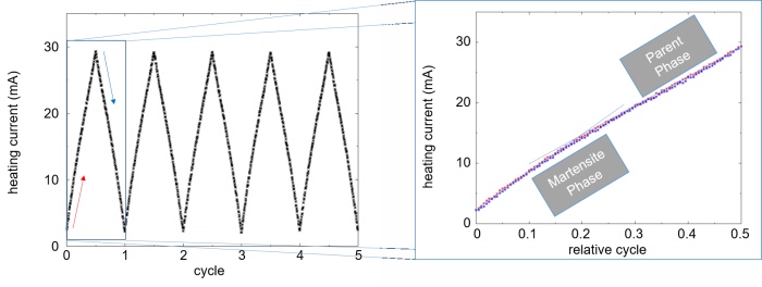
Fig. 1 The heating current profile from the heat-treated shape memory microwire without glass coating with 0.1 Hz triangular signal.
Acknowledgments
This work was supported by Slovak VEGA 2/0086/22 and VEGA 1/0180/23.
References
[1] L. Frolova et al., “Reversible structural transition in monocrystalline Ni2FeGa microwires for shape-memory applications,” Mater. Sci. Eng. B Solid-State Mater. Adv. Technol., vol. 263, p. 114891, 2021, doi: 10.1016/j.mseb.2020.114891.
[2] R. Casati, F. Passaretti, and A. Tuissi, “Effect of electrical heating conditions on functional fatigue of thin NiTi wire for shape memory actuators,” Procedia Eng., vol. 10, pp. 3423–3428, Jan. 2011, doi: 10.1016/J.PROENG.2011.04.564.Speaker: Dr Limpat Nulandaya (Institute of Experimental Physics, Slovak Academy of Science) -
16:00
Onset of Magnetization Reversal in Glass-covered CoSiB Microwires 2h
The jumps detected in the single-peak and the double-peak GMI ratio dependences of glass-covered CoSiB microwires [1] have been identified as the complex shape pulses in a modified experiment of Sixtus and Tonks. The shape of the induced pulses is given by a combination of two processes: the irreversible movement of the single domain wall and the radial displacement of the transition region (90$^\circ$-domain). The numerically calculated magnetic flux changes connected with the three characteristic pulses have shown that complex pulses of the 2. and 3. type are connected with the increase in the magnetic flux, which corresponds to 10 $\%$ change in value compared to the pulse of 1. type. Finally, this change also proves our assumption that during the rapid onset of magnetization reversal in the soft ferromagnetic CoSiB microwires the combination of displacements of the two domain walls occurs.
Acknowledgements
This research was supported by the Slovak Research and Development Agency under contract No. APVV-16-0079, by VEGA grant No. 1/0350/24 from the Scientific Grant Agency of the Ministry for Education of the Slovak Republic, by the project “Support for the Research and Development Potential in the area of Transportation Vehicles” ITMS 2014+ Code 313011T557 and by Foundation Volkswagen Slovakia Grant No. 085/15_RT.
References
[1] J. Kravčák and P. Vrábel, “Magnetoimpedance of soft ferromagnetic CoSiB microwire suitable for sensor applications,” AIP Conference Proceedings. AIP Publishing, 2024. doi: 10.1063/5.0187659.
Speaker: Jozef Kravčák (Department of Physics, Faculty of Electrical Engineering and Informatics, Technical University of Košice, Slovakia) -
16:00
The Influence of Anisotropies on the Electric Voltage Induced in Microwires 2h
Amorphous glass-coated microwires are composite materials that consist of metallic core covered by a glass coating. It has been shown that the domain wall propagation in microwires is accompanied by induction of electric voltage at the ends of the wire [1] (Fig. 1a). It arises from a small circular component of the magnetization (Fig. 1a) that is introduced to microwires during their manufacturing process. Even though several studies [2] have been devoted to the origin of the induced voltage, it is still not clear how the voltage can be increased by tailoring of magnetic anisotropies.
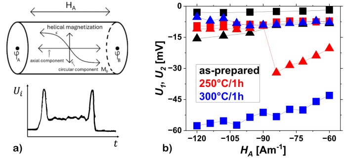
Fig. 1 a) Induced voltage is generated at the ends of the wire when the circular component of the magnetization changes. b) Dependence of $U_1$ and $U_2$ (voltage induced during DW depinnig - square symbols, and pinning - triangular symbols) on the magnitude of the axial magnetic field at different torsional annealing temperatures.
In this paper, we performed several thermal treatments of microwires aiming at very high electrical voltage in microwires. In the first part of the experiment, the effect of a transverse magnetic field on the dynamics of the domain walls is analyzed. The transverse field has the most pronounced effect on the voltage induced by the domain wall pinning at the end of the microwire. Torsional annealing of microwires significantly increases the induced voltage at the ends of the microwire, with higher annealing temperatures causing a larger increase (Fig. 1b). Stress-annealing does not increase the voltage caused by the depinning and pinning of the domain wall at the ends of the microwire but increases it during its propagation. Measurements of hysteresis loops at multiple points along the microwire show that the domain structure varies along the microwire. The closure domain structure at the ends of the microwire results in a distinct difference in the shape of the loops compared to the rest of the microwire. This work contributes to a better understanding of the phenomena in microwires and to the optimization of their use in real-world applications.
Acknowledgements
This work was supported by the Slovak Research and Development Agency under contract No. APVV-SK-FR-22-0016.
References
[1] A. F. Cobero et al., “Matteucci effect in glass coated microwires,” IEEE Transactions on Magnetics, vol. 35, no. 5. Institute of Electrical and Electronics Engineers (IEEE), pp. 3382–3384, 1999. doi: 10.1109/20.800531.
[2] A. Jiménez, E. Calle, J. A. Fernandez-Roldan, R. P. del Real, R. Varga, and M. Vázquez, “Matteucci Effect and Single Domain Wall Propagation in Bistable Microwire under Applied Torsion,” physica status solidi (a), vol. 218, no. 18. Wiley, Aug. 2021. doi: 10.1002/pssa.202100284.Speaker: Martin Eliáš (Technical University of Košice) -
16:00
Theoretical and Experimental Searching for New Free Rare-earths Permanent Magnets 2h
Utilizing permanent magnets (PM) in technological applications for information storage and green-energy generation is increasingly important. This necessitates the development of new magnetic materials that are more cost-effective and contain fewer critical components, such as rare earth (RE) elements. However, the systematic exploration of novel hard magnetic materials is a complex task due to the vast combinatorial space encompassed by the crystal structures and chemical compositions. Fortunately, applying structure-predicting techniques, specifically evolutionary or adaptive genetic algorithms in conjunction with ab initio calculations, presents a promising avenue for material discovery [1]. Notably, a recent computational screening of hard magnetic phases in the Fe-Ta binary system showcased the existence of metastable phases with intrinsic magnetic properties, such as high saturation magnetization and large magnetocrystalline anisotropy, which are ideal for PM materials [2].
Significantly, a predicted low energy Fe$_2$Ta structure (8 formula units) was experimentally observed in the Co-Ta binary family. The investigation into the thermodynamic stability of the (Co$_{1-x}$Fe$_x$)$_2$Ta alloys indicates a stable compound for an increased concentration of iron, and the experimental study verifies the synthesis of stable magnetic materials in the predicted phase. However, the new magnetic structure in the CoFeTa system does not exhibit a high enough Curie temperature for practical use as PM. This successful synergy between computational prediction and experimental validation paves the way for designing new magnetic materials.
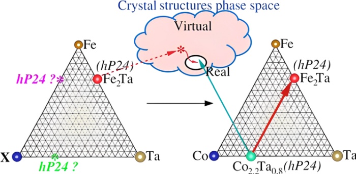
Fig. 1 A visual representation of the steps you need to take to create a new structure [3].
Acknowledgements
This research was partly funded by the Slovak grant agencies APVV-DS-FR-19-00-45, VEGA 1/0404/21, VEGA 1/0180/23, and VEGA 1/407/24.
References
[1] S. Arapan, P. Nieves, and S. Cuesta-López, “A high-throughput exploration of magnetic materials by using structure predicting methods,” Journal of Applied Physics, vol. 123, no. 8. AIP Publishing, Feb. 28, 2018. doi: 10.1063/1.5004979.
[2] S. Arapan, P. Nieves, H. C. Herper, and D. Legut, “Computational screening of Fe-Ta hard magnetic phases,” Physical Review B, vol. 101, no. 1. American Physical Society (APS), Jan. 21, 2020. doi: 10.1103/physrevb.101.014426.
[3] S. Arapan et al., “From virtual to reality: A practical route to design new materials,” Physical Review Research, vol. 6, no. 2. American Physical Society (APS), Apr. 09, 2024. doi: 10.1103/physrevresearch.6.023036.Speaker: Dr Andrea Dzubinska (CPM-TIP, Pavol Jozef Šafárik University, Košice, Slovakia) -
16:00
Thermal Stability of Soft Magnetic Fe-based Alloy studied by In-situ High-Energy Synchrotron Radiation 2h
Fe-based metallic glasses (MGs) exhibit superior soft magnetic properties such as a very low coercivity and power losses, a low magnetostriction and a high permeability [1]. Their magnetic properties can be further optimized by modification of post-processing conditions, such as temperature and duration of heat treatment. Structural characterization of MGs at the atomic level represents an ambitious task. The atomic arrangement in amorphous alloys is still not well understood compared with the well-defined long-range order in crystalline materials. Experimental methods like X-ray diffraction, transmission electron microscopy, small angle X-ray scattering, X-ray absorption spectroscopy and Mössbauer spectroscopy are usually applied for structural investigations of metallic glasses. However, all these experimental techniques suffer from limited brightness of the sources they use. This in turn implies rather low level of signal, which is inherent to highly disordered materials such as MGs. With the advent of 3rd generation synchrotron radiation sources and recent technological breakthroughs in photon detectors it is possible to acquire high-quality scattering data enabling quantitative study of local atomic structure of MGs. It has been recently demonstrated that the high energy X-ray scattering of synchrotron radiation can be used to track tiny structural changes in the structure of metallic glasses when exposed to thermal [2] or mechanical loading [3].
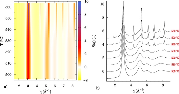
Fig. 1 a) Series of structure factors $S(q)$ of the Vitroperm alloy acquired during constant rate heating in-situ experiment. b) Comparison of selected $S(q)$ in the vicinity of crystallization. Sharp peaks correspond to the Bragg reflections of Fe$_{3}$Si cubic phase.
In this work we demonstrate the advantage of high-energy synchrotron radiation in studying changes in local atomic structure of Fe-base metallic glass (Vitroperm-800) induced by thermal loading. In the first part we present data obtained by thermally cycling the Vitroper-800 alloy in the temperature region well below its crystallization temperature $T_{x}$. Obtained data suggest irreversible structural changes which are fingerprint of amorphous structure relaxation. When performing constant rate (10 $^\circ$C/min) heating in-situ experiment from 20 up to 560 $^\circ$C, initially amorphous alloy undergoes crystallization at around $T_{x}$ = 515(5) $^\circ$C, which is in perfect agreement with earlier results. Above crystallization temperature the Bragg peaks stemming from Fe$_{3}$Si cubic phase are clearly visible (see Fig.1). To quantitatively characterize the mean grain size of Fe$_{3}$Si nanocrystals as a function of temperature (above $T_{x}$) analysis based on pair distribution function (PDF) was employed. It turns out that PDF approach is robust, and growth of ultra small grains can be reliably detected in the early stages of nanocrystal formation.
Acknowledgements
Vitroperm-800 alloy in the form of thin ribbon was kindly provided by Dr. G. Herzer from VACUUMSCHMELZE GmbH Hanau, Germany. This research was financially supported by a Slovak Scientific Grant Agency VEGA (project No. VEGA 1/0638/24).
References
[1] M. E. McHenry, M. A. Willard, and D. E. Laughlin, “Amorphous and nanocrystalline materials for applications as soft magnets,” Progress in Materials Science, vol. 44, no. 4. Elsevier BV, pp. 291–433, Oct. 1999. doi: 10.1016/s0079-6425(99)00002-x.
[2] H. F. Poulsen, J. A. Wert, J. Neuefeind, V. Honkimäki, and M. Daymond, “Measuring strain distributions in amorphous materials,” Nature Materials, vol. 4, no. 1. Springer Science and Business Media LLC, pp. 33–36, Dec. 19, 2004. doi: 10.1038/nmat1266.
[3] J. Bednarcik, S. Michalik, V. Kolesar, U. Rütt, and H. Franz, “In situ XRD studies of nanocrystallization of Fe-based metallic glass: a comparative study by reciprocal and direct space methods,” Physical Chemistry Chemical Physics, vol. 15, no. 22. Royal Society of Chemistry (RSC), p. 8470, 2013. doi: 10.1039/c3cp44445g.Speaker: Ms Ravneet Kaur (Pavol Jozef Safarik University in Kosice, Faculty of Science, Institute of Physics) -
16:00
Thermally Activated Relaxation of Stress-Induced Anisotropy in VITROPERM-800 2h
Annealing of amorphous Vitroperm-800 alloy in the form of thin ribbons under tensile stress is very effective way of achieving huge value of magnetic anisotropy, which may well exceed the value of magneto-crystalline constant (8 kJ/m$^3$) of Fe-Si crystalline phase [1]. As a result of such thermo-mechanical treatment ribbons reveal perfectly linear hysteresis loop with constant slope (permeability) which can be controlled by applied stress. It has been shown in our recent work [2] that such stress induced anisotropy (SIA) is because Fe$_{3}$Si nanocrystalline grains growing in the tensile direction have a higher value of the lattice spacing as in case of transversal direction, where opposite behavior is seen. Furthermore it was demonstrated that the strain partitioning among different Bragg reflections of Fe$_{3}$Si phase is not even, and the magnitude of the SIA for a given set of Bragg reflections $\{hkl\}$ is inversely proportional to its Young’s modulus $E_{hkl}$.
In this work the emphasis was placed at the study of relaxation process of SIA during thermal cycling. Nanocrsytalline ribbons with different levels of SIA were prepared by annealing amorphous Fe$_{73.6}$Cu$_{1}$Nb$_{3}$Si$_{15.5}$B$_{6.9}$ alloy at two different stresses, i.e. 14 MPa and 482 MPa. Temperature-time behavior of the SIA was recorded during in-situ XRD experiments when exposing specimen to thermal cycling (20 -> 550 -> 100 -> 550 $^\circ$C). In-situ XRD experiments were done at the P02.1 beamline of the PETRA III synchrotron storage ring at DESY in Hamburg, Germany. It was found that the relaxation process starts with an increase in the values of SIA across all Bragg reflections of Fe$_{3}$Si cubic phase. After reaching temperature of 400 $^\circ$C magnitude of the SIA tends to decrease with temperature increasing up to 500 $^\circ$C (see Fig.1). Following cooling down to 100 $^\circ$C and heating back to 500 $^\circ$C yield, within an experimental error, similar behaviors. Similar trends, however with different magnitudes of SIA, are observed for all Bragg reflections of Fe$_{3}$Si cubic phase.
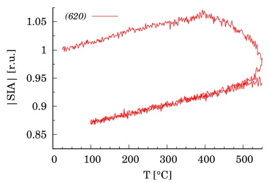
Fig. 1 Temperature dependence of the relative magnitude |SIA| as determined for the (620) Bragg reflection of Fe$_{3}$Si cubic phase.
Acknowledgements
Vitroperm-800 alloy in the form of thin ribbon was kindly provided by Dr. G. Herzer from VACUUMSCHMELZE GmbH Hanau, Germany. This research was financially supported by a Slovak Scientific Grant Agency VEGA (project No. VEGA 1/0638/24).
References
[1] G. Herzer, V. Budinsky, and C. Polak, “Magnetic properties of nanocrystalline FeCuNbSiB with huge creep induced anisotropy,” Journal of Physics: Conference Series, vol. 266. IOP Publishing, p. 012010, Jan. 01, 2011. doi: 10.1088/1742-6596/266/1/012010.
[2] D. Yudina, M. Marsilius, and J. Bednarcik, “Structural aspects of stress-induced magnetic anisotropy in Fe-based nanocrystalline alloy,” Journal of Alloys and Compounds, vol. 960. Elsevier BV, p. 171011, Oct. 2023. doi: 10.1016/j.jallcom.2023.171011.Speaker: Dr Vladimír Girman (Pavol Jozef Safarik University in Kosice, Faculty of Science, Institute of Physics) -
16:00
Time-Resolved Observations of a Surface Domain Wall Pinning in Amorphous Glass-Coated Microwires 2h
Thin magnetic cylindrical wires attract considerable attention due to interesting features of a domain wall motion like absence of the Walker breakdown that prevents fast domain wall dynamics [1]. Amorphous glass-coated microwires are composite material, in which very high domain wall velocities have been observed [2]. Owing to the amorphous state of wires, the magneto crystalline anisotropy vanishes. Recently, it was shown that the axial magnetic anisotropy resulting from rapid quenching has comparable strength, leading to a tilted domain wall orientation [3]. It is an open question of how the tilted domain wall in cylindrical wires moves with application of mechanical torsion stresses.
Magneto-optical Kerr effect is used to visualize a surface magnetization dynamics in microwires. The domain wall is stabilized by two opposite magnetic fields, resulting in effective one-dimensional potential well. Periodic back-and-forth motion of the well is used to synchronize the domain wall position with MOKE imaging and direct time-resolved images of a surface magnetism are performed. In contrast to previous measurements, mechanical torsion is applied to the microwire. Our spatial imaging of a surface domain wall shape reveals two typical types of a DW distortions. In highly magnetostrictive alloy (e.g. FeSiB), the mechanical torsion stress results in a screw-like distortions of a DW (Fig. 1). On the other side, microwires with reduced magnetostriction exhibits almost zero distortion of a domain wall shape. In both cases, the magnetostriction plays an essential role because the mechanical distortion is always smaller than the distortion of a DW. Time-resolved observation of a magnetization dynamics allows optimization of the giant-magnetoimpedance effect (GMI) in highly sensitive sensors.
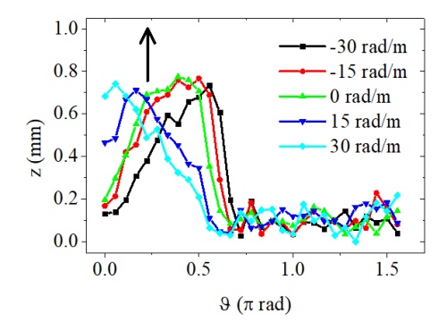
Fig.1 Snapshots of domain wall profiles for specific angles of torsion in FeSiB microwire.
References
[1] M. Yan, A. Kákay, S. Gliga, and R. Hertel, “Beating the Walker Limit with Massless Domain Walls in Cylindrical Nanowires,” Physical Review Letters, vol. 104, no. 5. American Physical Society (APS), Feb. 01, 2010. doi: 10.1103/physrevlett.104.057201.
[2] P. Klein, R. Varga, G. A. B. Confalonieri, and M. Vazquez, “Domain Wall Dynamics in Amorphous and Nanocrystalline FeCoMoB Microwires,” Journal of Nanoscience and Nanotechnology, vol. 12, no. 9. American Scientific Publishers, pp. 7464–7467, Sep. 01, 2012. doi: 10.1166/jnn.2012.6526.
[3] O. Vahovsky, R. Varga, and K. Richter, “Experimental method for surface domain wall shape studies in thin magnetic cylinders,” Journal of Magnetism and Magnetic Materials, vol. 483. Elsevier BV, pp. 266–271, Aug. 2019. doi: 10.1016/j.jmmm.2019.03.015.Speaker: Kornel Richter (Department of Physics, Faculty of Electrical Engineering and Informatics, Technical University of Kosice)
-
16:00
-
08:00
→
09:00
-
-
08:00
→
09:00
Registration 1h Lecture Hall
Lecture Hall
Košice, Slovakia
Doktora Kostlivého 576/1 -
09:00
→
10:30
WED: Session 4 Lecture Hall
Lecture Hall
Košice, Slovakia
Doktora Kostlivého 576/1Convener: Rafael Perez del Real (Institute of Materials Science of Madrid, ICMM-CSIC)-
09:00
Highly Sensitive Off-diagonal Magneto-Impedance Sensor System for Bio Magnetic Field Measurement 30m
Magnetization dynamics by pulse excitation in amorphous wire is limited in the surface layer by skin effect due to magnetic rotation. We have constituted highly sensitive linear micro magnetic field sensors utilizing off-diagonal Magneto-Impedance (MI) effect [1]. Recently we have succeeded in producing pico-Tesla ($10^{-8}$ Oe) resolution MI sensors [2] due to ultra-low intrinsic magnetic noise of amorphous wire. Superconducting quantum interference deice (SQUID) have ultrasensitive, which have been utilized for bio-magnetic signals. For example, magnetocardiography (MCG) is a noninvasive technology that measures the magnetic field of the heart. We have tried to measure MCG signal using MI gradiometer. Figure 1 shows magnetic signal at 4 cm left the pit of the stomach. The subject was a man. A distance between from sensor head to a body surface is about 10 mm. The magnetic signal shown was averaged for 20 cycles. The magnetic wave form was well corresponding to the ECG wave form.
Meanwhile, we have also tried MEG (magnetoencephalography) measurements of spontaneous brain activity (alpha rhythm) via pico-tesla resolution MI sensor. It was evaluated that Alpha rhythm have a maximum amplitude of approximately 8 pT, with main frequency components at 9-13 Hz, which depends on state of eye closing or opening.
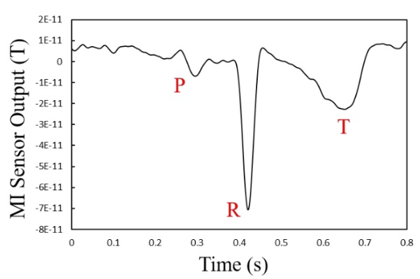
Fig. 1 MCG signals in averaging over 20 cycles at 25 mm to the left of the pit of the stomach.
Acknowledgements
This work was partly supported by JST A-STEP Grant Number JPMJTR221D, Japan.
References
[1] S. Gudoshnikov, N. Usov, A. Nozdrin, M. Ipatov, A. Zhukov, and V. Zhukova, “Highly sensitive magnetometer based on the off‐diagonal GMI effect in Co‐rich glass‐coated microwire,” physica status solidi (a), vol. 211, no. 5. Wiley, pp. 980–985, Feb. 14, 2014. doi: 10.1002/pssa.201300717.
[2] T. Uchiyama and J. Ma, “Development of pico tesla resolution amorphous wire magneto-impedance sensor for bio-magnetic field measurements,” Journal of Magnetism and Magnetic Materials, vol. 514. Elsevier BV, p. 167148, Nov. 2020. doi: 10.1016/j.jmmm.2020.167148.Speaker: Tsuyoshi Uchiyama (Department of Electronics, Graduate School of Engineering; Nagoya University,) -
09:30
From Theory to Experiment. Investigation of the Spectral Density of the Equivalent Magnetic Noise of PHMR Sensors. 15m
Classically, the ultimate or intrinsic noise of a sensor is studied/given by the help of the Fluctuation Dissipation Theorem (FDT). Here, we have investigated the magnetic noise of the Planar Hall MagnetoResistance (PHMR) sensor [1] based on this phenomenological physical description [2] and experimental measurements. Indeed, the ellipse surface given by the sensor response, lying $B$ (sensed induction) versus $H$ applied magnetic field, is homogenous of an energy taking account of the magnetic material sensor volume. It helps to quantify the dissipation, so losses. In a parallel way, we have measured the sensor response versus the applied field to evaluate the equivalent magnetic noise in terms of spectral density. The latter have been compared to classical noise spectral density measurements. Result yields to fix the ultimate noise of the sensor based on the given sensor development and quantified the dominant sources versus bias conditions and frequency range, clearly. The physics underlying the experimental results is shown to be consistent, up to a certain extent, with the FDT. It yields
$S_{BB}\approx \frac{2k_{B}T}{\Omega\pi f} \frac{B_{sat}}{M_{S}}\left(\frac{\chi''(f)}{\chi'}\right) + 4k_{B}TR\left(\frac{R}{\Delta R}\frac{B_{sat}}{V_{0}} \right)^2 + kS_{TT}(f) \quad \mathrm{[T^2/Hz]}$
where $S_{BB}$, $k_{B}$, $T$, $B_{sat}$, $f$, $M_{S}$, $\chi$, $R$, $\Delta R/R$, $V_{0}$, $k$ and $S_{TT}$ are the equivalent magnetic noise power spectral density, the vacuum permeability, the temperature, the saturate induction field of free hard axis layer, the frequency, the saturation magnetization of the free layer (permalloy), the loss terms (real and imaginary parts), the bridge resistance, the magnetoresistance coefficient, the bias voltage of the bridge, a factor in units of T/K and the power spectral density of the environmental temperature fluctuations, respectively.
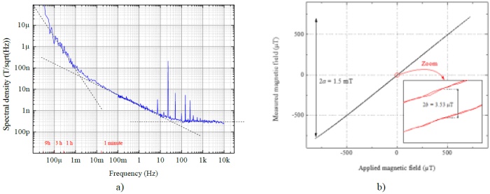
Fig. 1 (a) Equivalent magnetic noise spectral density measurement of a PHMR sensor (The peak signal at 23 Hz is a reference, others peaks are induced by the power line). The dashed lines correspond to evaluate noise based on modeling and hypotheses. (b) Example of a measured ellipse (equivalent sensed induction field versus applied magnetic field @ 0.03 Hz) used to extract $\chi'$ and $\chi''$ values.
References
[1] B. Lim et al., “Advances and key technologies in magnetoresistive sensors with high thermal stabilities and low field detectivities,” APL Materials, vol. 10, no. 5. AIP Publishing, May 01, 2022. doi: 10.1063/5.0087311.
[2] N. Smith and P. Arnett, “White-noise magnetization fluctuations in magnetoresistive heads,” Applied Physics Letters, vol. 78, no. 10. AIP Publishing, pp. 1448–1450, Mar. 05, 2001. doi: 10.1063/1.1352694.Speaker: Christophe DOLABDJIAN (GREYC - Normandie Univ. UNICAEN ENSICAEN CNRS) -
09:45
Magnetic X-Y Position Sensor 15m
Flat 2-D alignment sensors are required by the printing industry for precise mounting of the plate on the drum to avoid position misalignment in the overlapped patterns. Another application is for the coil alignment for contactless charging. High linearity is not required as the sensor serves as a null indicator in the automatic alignment process. The sensor should be very thin and the moving part should be passive target. Existing X-Y optical position systems such as [1] achieve high accuracy, but they are sensitive to dirt. Capacitive sensors such as [2] are sensitive to tilt, which cannot be avoided in industrial applications.
Our novel sensor consists of flat coil system on the stationary part and flat magnetically soft cross-shaped armature on the moving part as shown in Fig. 1a. One excitation and four 20-turns PCB pickup coils are used. The output voltage is measured by synchronous detector to suppress the interference from external fields and indicate the displacement direction. The temperature dependence and the influence of liftoff will be suppressed by using ratiometric output. The sensor simulated output for 0.5 mm thick FeSi armature is shown in Fig. 1b). The performance was confirmed experimentally. In the full paper we will compare simulations to experimental results for both FeSi and nanocrystalline armatures for frequencies up to 1 MHz. We will also demonstrate the influence of the eddy currents in the armature as well as possibilities of using non-magnetic armature. The sensor geometry will be further optimized for sensitivity and linearity for arbitrary movement direction.
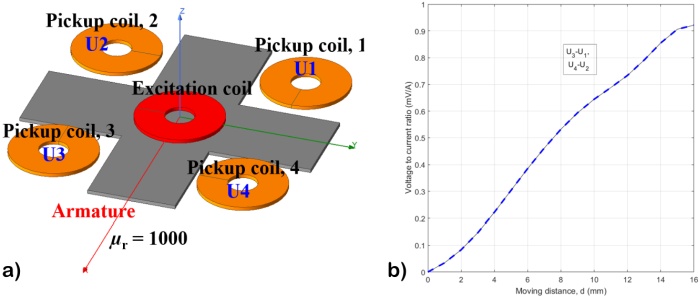
Fig. 1 a) Magnetic x-y position sensor b) sensor output for FeSi armature movement in x direction - FEM simulation.
Acknowledgements
This work was supported by GACR project 24-12705S Novel Magnetic Position Sensor.
References
[1] J.-A. Kim, J. W. Kim, C.-S. Kang, and J. Jin, “Note: An absolute X-Y-$\Theta$ position sensor using a two-dimensional phase-encoded binary scale,” Review of Scientific Instruments, vol. 89, no. 4. AIP Publishing, Apr. 01, 2018. doi: 10.1063/1.5022717.
[2] S. B. Field and J. Barentine, “Capacitive position sensor with simultaneous, linear X–Y readout,” Review of Scientific Instruments, vol. 71, no. 6. AIP Publishing, pp. 2603–2607, Jun. 01, 2000. doi: 10.1063/1.1150656.Speaker: Pavel Ripka (CVUT FEL (Czech Technical University, Faculty of Electrical Engineering)) -
10:00
CMOS-based Micro-fluxgate with Racetrack Core and Solenoid Coils 15m
This work introduces a miniaturized fluxgate sensor integrated on a chip fabricated using CMOS technology. The sensor uses a "acetrack" shape of the core, laser-cut out of a 25 $\mu$m thick sheet of VITROVAC 6025F amorphous metal. The structure is Vacquier type, with solenoid excitation and sensing coils. The coils are fabricated using chip’s metal layer and bonding wires. The sensing coil winding has 60 turns, and the excitation coils have 40 turns in total. TSMC D35 technology was used for fabrication. Dimensions of the chip are 8 mm $\times$ 2.7 mm (21.6 mm$^{2}$).
In open-loop operation, the linear range of the sensor is $\pm200\,\mu \mathrm{T}$. Maximum sensitivity of around 5000 V/T is reached at an excitation frequency of 1.5 MHz. The current required to fully saturate the core is around 110 $\mathrm{mA_{RMS}}$ when using sinewave excitation, resulting in 300 mW power dissipation on the excitation coil. Core loss is 100 mW at 1 MHz excitation. Noise at 1 Hz may be as low as 2 $\mathrm{nT}/\sqrt{Hz}$ depending on excitation signal parameters. Typical offset is in order of 100 nT. Possible applications of this sensor include electronic compass, contactless current measurement, and measuring position relative to permanent magnet.
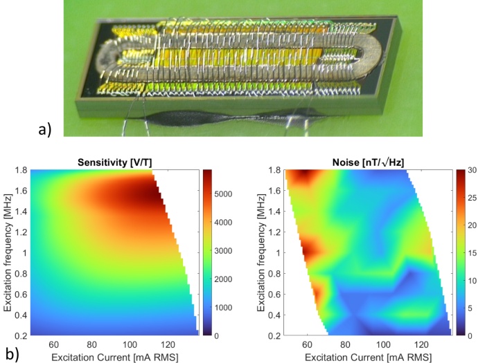
Fig. 1 a) Microscope photo of the micro-fluxgate. b) Measured characteristics of the micro-fluxgate.
Acknowledgements
The chips were fabricated in cooperation with Taiwan Semiconductor Research Institute (TSRI).
Speaker: Jiří Maier (Czech Technical University in Prague) -
10:15
Vertical Integration of TMR Sensors for Enhanced Detectivity 15m
3D Packing emerges as a novel method to push the detectivity of TMR sensors to state-of-the-art pT detectivities by vertically connecting TMR sensors in parallel. Diverging from conventional sensor design strategies that rely on creating 2D arrays, this innovative approach preserves a compact footprint crucial for high spatial resolution where xMR technologies excel [1].
In this work, we demonstrate a decrease in detectivity with the number of vertical iterations, due to the $1/\sqrt{Z}$ dependency as expressed in equation 1, obtained from the TMR sensor's sensitivity through magneto-electrical measurements and its noise spectra, following the models described by [2].
$D= \frac{dH}{dri}\sqrt{\left(4k_{b}Tr+ \frac{\alpha'_{H}r^{2}i^{2}}{f} \right)\frac{1}{XYZ}} \quad (1)$
Due to an increase in surface roughness and topography, which occurs upon overlapping several layers of patterned films during the microfabrication steps, different packing strategies are implemented to reduce it: shifted and alternating packing (Fig. 1a). These strategies try to minimize topography in the areas of the MTJ pillars and consist of different alignments between bottom electrodes and pillar structures, thus leading to different detectivity results. Here we describe the process challenges for the vertical integration of the devices, and their impact on the sensor sensitivity and overall detectivity.
Comparing with a single TMR, two levels packed TMR sensors show lower detectivity across the measured spectra, between 5 and 100 kHz (Fig. 1b). Additionally, the topography control strategies lead to a lower detectivity overall, obtaining a detectivity of 102 nT.Hz$^{1/2}$ and 90 nT.Hz$^{1/2}$ at 10 Hz for the alternating and shifted strategies.
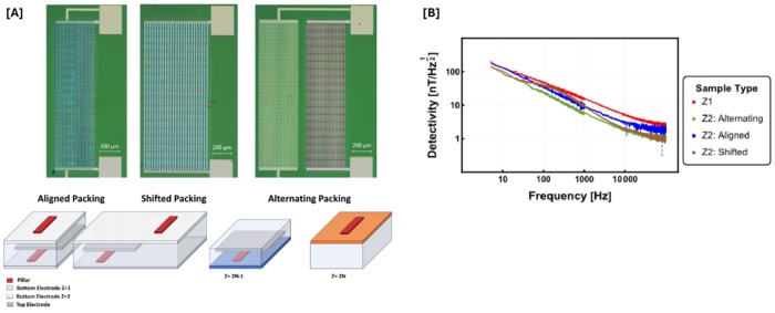
Fig. 1 a) Schematic of the different packing strategies: aligned, shifted, and alternating strategies. b) Corresponding detectivity spectra between 5 and 100kHz for Z=1 and Z=2.
Acknowledgements
The authors acknowledge BASE (UIDB/0536/2020), PROGRAMATICO (UIDP/0536/2020) Programs.
References
[1] M. Silva, F. Franco, D. C. Leitao, S. Cardoso, and P. P. Freitas, “Two-dimensional arrays of vertically packed spin-valves with picoTesla sensitivity at room temperature,” Scientific Reports, vol. 11, no. 1. Springer Science and Business Media LLC, Jan. 08, 2021. doi: 10.1038/s41598-020-79856-0.
[2] Z. Q. Lei, G. J. Li, W. F. Egelhoff, P. T. Lai, and P. W. T. Pong, “Review of Noise Sources in Magnetic Tunnel Junction Sensors,” IEEE Transactions on Magnetics, vol. 47, no. 3. Institute of Electrical and Electronics Engineers (IEEE), pp. 602–612, Mar. 2011. doi: 10.1109/tmag.2010.2100814.Speaker: Filipe Monteiro (INESC Microsistemas e Nanotecnologias (INESC MN))
-
09:00
-
10:30
→
11:00
Coffee break 30m MINERVA
MINERVA
Doktora Kostlivého 576/1 -
11:00
→
12:30
WED: Session 5 Lecture Hall
Lecture Hall
Košice, Slovakia
Doktora Kostlivého 576/1Convener: Dr Ivan Škorvánek (Institute of Experimental Physics SAS)-
11:00
Magnetic Actuation based Mattertronic Circuitry Platform for Multiplexed Single Cells Analysis and Beyond 30m
The precise delivery of bio-functionalized matters is of great interest in emerging biomedical technologies from the fundamental and applied viewpoints. Particularly, most existing single cell platforms are unable to achieve large scale operation with flexibility on cells and digital manipulation towards multiplex cell tweezers. Recently, the flexibility of magnetic shuttling technology using nano/micro-scale magnets for the circuitry manipulation of bio-carriers has gained significant advances for a versatile living cell manipulation tasks [1,2,3]. Herein, let’s call “spintrophoresis” using micro-/nano-sized Spintronic devices rather than “magnetophoresis” using bulk magnet. Especially analogy of IC chip via the electronic carriers of electron and hole has been implemented in the integrated spintrophoretic circuit platform with passive and active circuitry elements of collector, resistor, diode, capacitor and gating transistor of magnetic and pseudo-diamagnetic bio-carriers (mattertronics: matter+tronics), using remote magnetic actuation.
In fact, each cells have the heterogeneous bio-chemical characteristics, as well as different drug resistance. As for the realization of future personalized diagnosis and care considering the individual cell heterogeneity, primary hurdle is development of multiexed cell manipulation method. Here, magnetic assisted multiplexed cell array will offer the promising versatile platform for multiplexed cell tweezering, compared with the other methods including current FACS and optical tweezers. Here I will introduce the novel spintronic devices and their integrated platform for versatile multiplexed tweezers of living cells, which enables a portable multiplex cell manipulation platform for electro-bio-chemical analysis in individual cellular level.
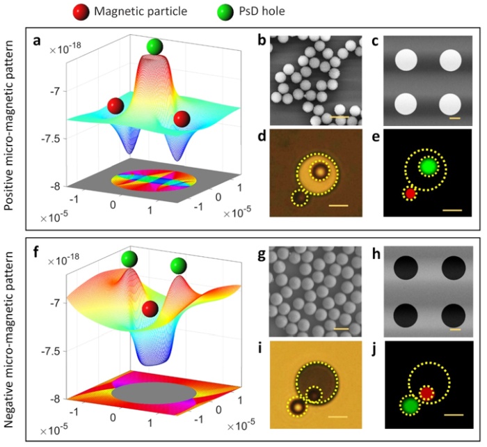
Fig. 1 Magnetic potential energy over micro-magnetic pattern for magnetic and PsD holes [4].
Acknowledgments
This research was supported by the National Research Foundation of Korea (NRF) grant funded by the Korean Government (MSIT) (2018R1A5A1025511).
References
[1] Y. Kang et al., “Tailored Micromagnet Sorting Gate for Simultaneous Multiple Cell Screening in Portable Magnetophoretic Cell‐On‐Chip Platforms,” Advanced Functional Materials. Wiley, Mar. 05, 2024. doi: 10.1002/adfm.202312875.
[2] H. Kim et al., “Magnetophoretic Decoupler for Disaggregation and Interparticle Distance Control,” Advanced Science, vol. 8, no. 12. Wiley, May 2021. doi: 10.1002/advs.202100532.
[3] B. Lim et al., “Magnetophoretic circuits for digital control of single particles and cells,” Nature Communications, vol. 5, no. 1. Springer Science and Business Media LLC, May 14, 2014. doi: 10.1038/ncomms4846.
[4] S. R. Goudu et al., “Mattertronics for programmable manipulation and multiplex storage of pseudo-diamagnetic holes and label-free cells,” Nature Communications, vol. 12, no. 1. Springer Science and Business Media LLC, May 21, 2021. doi: 10.1038/s41467-021-23251-4.Speaker: Prof. CheolGi KIM (DGIST) -
11:30
Pulse Monitoring using a Magnetic Sensor and its Detection Mechanism 15m
Continuous non-invasive monitoring of vital signs, such as heart rate and blood pressure, is essential for preventive care and managing chronic conditions. Techniques like photoplethysmography (PPG) and electrocardiogram are widely used to extract these signals, but they have limitations in terms of working conditions due to the requirement of good skin contact.To address the limitations of existing techniques, we have developed a pulse detection device based on a magnetic sensor which can be applied to various conditions that cannot be accessed by PPG [1]. The device in its simplest form comprises only a small magnet and a magnetic sensor (Fig.1a), which can be attached to either fingertips or wrist. When blood flows the magnetic field surrounding the magnet changes subtly (Fig.1b), which can be detected by the nearby magnetic sensor. Through a series of experiments and simulations, we validated that the detected signals stem from the vibration of the magnet induced by blood flow, dismissing the previously suggested mechanism linked to alterations in the magnetic properties of blood under varying oxygenation states [2]. The correlation between the magnetic and vibration signal is in the range of 95-99$\%$ (Fig.1c). The device could be used in conditions which are challenging for existing pulse detectors and might also have its application extended to blood pressure measurement.
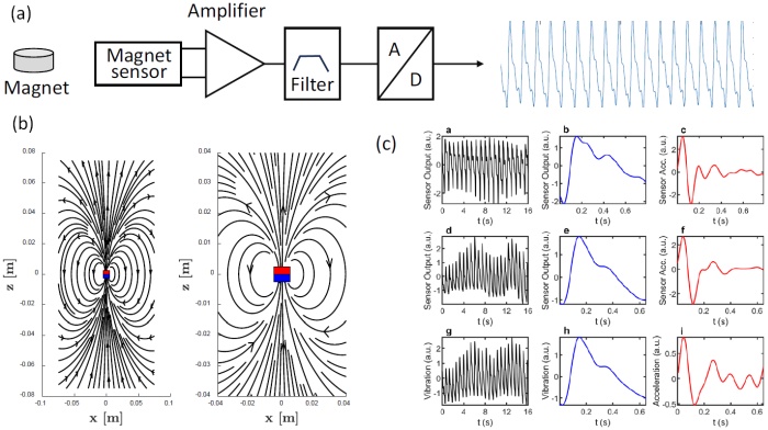
Fig. 1 a) Schematic diagram of the pulse detection device based on magentic sensors; (b) calculated magentic field surrounding an N52 magnet with a diameter of 1cm and thickness of 5 mm; (c) upper and middle panels: detected magnetic signals, lower panel: detected vibration signal (same subject as the middle panel).
References
[1] H. Shen, X. Gu, and Y. Wu, “A fingertip-type magnetic pulse detection device for unusual monitoring conditions,” Communications Engineering, vol. 2, no. 1. Springer Science and Business Media LLC, Jul. 28, 2023. doi: 10.1038/s44172-023-00102-2.
[2] C. T. Phua, G. Lissorgues, and B. Mercier, “Non-invasive Acquisition of Blood Pulse Using Magnetic Disturbance Technique,” IFMBE Proceedings. Springer Berlin Heidelberg, pp. 786–789, 2009. doi: 10.1007/978-3-540-92841-6_193.Speaker: Yihong Wu (National University of Singapore) -
11:45
Influence of Tensile Stress on Scattering Parameters of Continuous Ferromagnetic Microwire Embedded into Reinforced Composites 15m
Magnetic microsensors have been proposed for the monitoring of various processes and functionalities for diverse industries and soft magnetic materials can be used for a large variety of sensors [1]. Amorphous ferromagnetic and nanocrystalline wires show interesting properties for giant magnetoimpedance (GMI) or domain wall propagation. The effectiveness of the GMI is connected to the applied tension [2].
Studies of UPV/EHU have shown that specifically designed anisotropic magnetic fibers show a tension sensitive GMI, adequate for the monitoring of variation in tension and material deformation [3]. Also, in situ studies of the evolution of hysteresis cycle and reflection and transmission parameters were performed during matrix polymerization [4]. Low frequency modulated ac magnetic field was used to distinguish the microwave signal originated by microwires in carbon reinforced composites [5].
In this work, continuous microwires were integrated into a glass fiber reinforced composite (GFRP) coupon. Also, a vector network analyzer (VNA) was coupled to a universal testing machine. Therewith, scattering parameters were determined by means of free space measurements, while simultaneously, test specimens were submitted to tensile stresses.
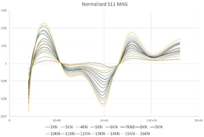
Fig. 1 Normalized reflection scattering parameter S11.
A clear and strong dependence of scattering parameters with tensile stress has been identified, considered as a baseline for new detection methods to be developed. It allows to monitor, in a non-destructive and contactless operation, glass reinforced composites with embedded continuous ferromagnetic microwires with magnetic sensitivity to tensile stress variation.
Acknowledgements
This work was supported by the EU through “INFINITE” (HORIZON-CL5- 2021-D5-01-06) project, and by the Government of the Basque Country through Elkartek (ZE-KONP and MOSINCO) projects.
References
[1] P. Ripka and G. Vértesy, “Sensors based on soft magnetic materials Panel discussion,” Journal of Magnetism and Magnetic Materials, vol. 215–216. Elsevier BV, pp. 795–799, Jun. 2000. doi: 10.1016/s0304-8853(00)00291-2.
[2] A. Zhukov, M. Ipatov, and V. Zhukova, “Advances in Giant Magnetoimpedance of Materials,” Handbook of Magnetic Materials. Elsevier, pp. 139–236, 2015. doi: 10.1016/bs.hmm.2015.09.001.
[3] A. F. Cobeño, A. Zhukov, J. M. Blanco, V. Larin, and J. Gonzalez, “Magnetoelastic sensor based on GMI of amorphous microwire,” Sensors and Actuators A: Physical, vol. 91, no. 1–2. Elsevier BV, pp. 95–98, Jun. 2001. doi: 10.1016/s0924-4247(01)00502-7.
[4] A. Allue et al., “Smart composites with embedded magnetic microwire inclusions allowing non-contact stresses and temperature monitoring,” Composites Part A: Applied Science and Manufacturing, vol. 120. Elsevier BV, pp. 12–20, May 2019. doi: 10.1016/j.compositesa.2019.02.014.
[5] V. Zhukova et al., “Free Space Microwave Sensing of Carbon Fiber Composites With Ferromagnetic Microwire Inclusions,” IEEE Sensors Letters, vol. 8, no. 1. Institute of Electrical and Electronics Engineers (IEEE), pp. 1–4, Jan. 2024. doi: 10.1109/lsens.2023.3337071.Speaker: Rafael Garcia-Etxabe (GAIKER Technology Centre, Basque Research and Technology Alliance (BRTA), Spain) -
12:00
Magnetic Nanoparticles Detection with GMI Effect in Micro Fluidic System 15m
Magnetic nanoparticles detection in fluid media is a promising technique for identifying biomolecules, antigens, pollutants, etc. that can be attached to their properly functionalised surface. Magnetic detection allows non-contact sensing, and many different effects, including magnetophoresis, magnetoresistance, magneto-impedance, optical and mechanical resonance ones can be exploited to address the specific problem and to achieve the desired sensitivities.
In this work, we aim at demonstrating the working principle of a magnetic nanoparticles detection system based on the giant magneto-impedance effect and exploiting a micro fluidic system. The experimental setup allows to control the flow (velocity, pressure) of a fluid into a micro-pipes system. A Fe$_{73.5}$Cu$_1$Nb$_3$Si$_{13.5}$B$_9$ microwire is inserted into a portion of the micro-pipes, with electrical contacts to inject an alternating current into the microwire (see Figure 1, left). An external solenoid provides a DC magnetic field directed parallel to the microwire axis. The fluid consists of water in which known concentrations of magnetic nanoparticles are dispersed: either CoFe$_2$O$_4$ nanoparticles synthesised by co-precipitation method, or Micromod Partikeltechnologie GmbH commercial multicore superparamagnetic iron-oxide nanoparticles (SPIONs).
The water-dispersed nanoparticles flow along the micro fluidic system passing nearby the magnetic microwire. Its magneto-impedance effect is measured at constant electrical current frequency (1.5 MHz), as a function of the DC magnetic field applied with the solenoid. The voltage drop across the microwire is measured and its maximum variation between 0 and 12 kA/m applied field is mapped as a function of nanoparticles type and concentration, as shown in Figure 1 (right). The reciprocal interaction of the nanoparticles with microwire domain configuration is responsible for the different evolution of the GMI with concentration, which increases for SPIONs particles and decreases for harder Co-ferrites. The physical phenomena will be discussed in details.
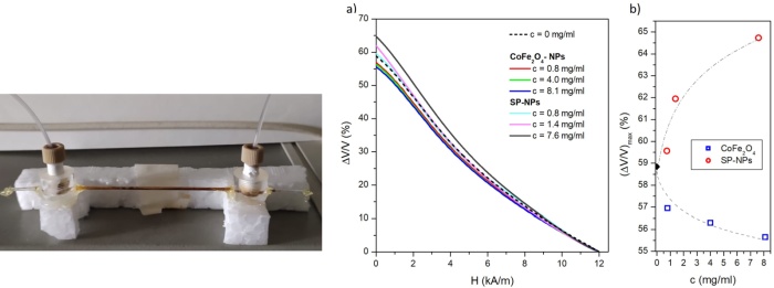
Fig. 1 Left: detail of the micro-pipes system with the magnetic microwire. Right: voltage drop across the microwire as a function of applied DC magnetic field, for different nanoparticles types and concentration, and as a function of concentration, for different nanoparticles types.
Acknowledgements
This work was partially funded by Italian Ministry for University and Research DM 737/2021.
Speaker: Marco Coïsson (INRIM) -
12:15
Microfluidic Device with Embedded AMR Sensors for the Detection of Magnetotactic Bacteria 15m
Magnetotactic bacteria are aquatic microorganisms able to swim along the Earth’s magnetic field lines thanks to an internal chain of magnetic nanoparticles that acts as a compass needle. These nanoparticles, called magnetosomes, are composed of a high purity crystalline magnetic core surrounded by a lipid bilayer membrane. For example, as a typical magnetotactic bacteria, the Magnetospirillum gryphiswaldense species can have up to 25 cuboctahedral magnetite (Fe$_{3}$O$_{4}$) particles, each measuring approximately 45 nm. This opens up the possibility of controlling their motion through external magnetic fields [1]. Being non-pathogenic makes them ideal for bio-applications such as detection and treatment of cancer through MRI, magnetic hyperthermia or targeted drug delivery [2]. To implement and improve these applications, their swimming mechanisms and response to external magnetic fields must be studied. While motility experiments often rely on the optical observation of the bacteria and on video recording for later analysis, we propose a different approach based on magnetic sensing, by detecting the stray field created by the magnetosome chain. The use of a device based on magnetic detection would enable a high level of integration as well as the potential development of a feedback loop for controlling bacteria trajectories.
In this work we describe the development of a microfluidic chip for the combined optical and magnetic detection of magnetotactic bacteria. The device consists of three series of magnetic microsensors integrated at the bottom of a fully transparent microfluidic channel. The fabrication process incorporates traditional microfabrication techniques such as photoresist lithography and sputtering deposition, as well as soft lithography using PDMS and SU-8. The microsensors are Permalloy-based anisotropic magnetoresistance (AMR) sensors. The size of the sensors, in the range of tens of microns, and their layout are determined by the compromise between the tiny size of the magnetotactic bacteria and the maximization of their response to the stray field of the magnetosome chain [3]. The microfluidic channel is patterned over the sensors ensuring proper alignment using SU-8 photoresist, and a final layer of flat PDMS is bonded on top to seal the device.
References
[1] S. Rismani Yazdi, R. Nosrati, C. A. Stevens, D. Vogel, P. L. Davies, and C. Escobedo, “Magnetotaxis Enables Magnetotactic Bacteria to Navigate in Flow,” Small, vol. 14, no. 5. Wiley, Dec. 04, 2017. doi: 10.1002/smll.201702982.
[2] M. L. Fdez-Gubieda, J. Alonso, A. García-Prieto, A. García-Arribas, L. Fernández Barquín, and A. Muela, “Magnetotactic bacteria for cancer therapy,” Journal of Applied Physics, vol. 128, no. 7. AIP Publishing, Aug. 17, 2020. doi: 10.1063/5.0018036.
[3] D. de Cos, N. Lete, M. L. Fdez-Gubieda, and A. García-Arribas, “Study of the influence of sensor permeability in the detection of a single magnetotactic bacterium,” Journal of Magnetism and Magnetic Materials, vol. 500. Elsevier BV, p. 166346, Apr. 2020. doi: 10.1016/j.jmmm.2019.166346.Speaker: Mx Nerea Lete (Universidad del País Vasco (UPV/EHU))
-
11:00
-
12:30
→
12:45
Conference PHOTO 15m Lecture Hall
Lecture Hall
Košice, Slovakia
Doktora Kostlivého 576/1 -
12:45
→
14:00
LUNCH 1h 15m SOKRATES
SOKRATES
Doktora Kostlivého 576/1 -
14:00
→
15:45
WED: Session 6 Lecture Hall
Lecture Hall
Košice, Slovakia
Doktora Kostlivého 576/1Convener: Victor Sverdlov (CDL for NovoMemLog, IuE, TU Wien)-
14:00
Towards Reprogrammable Magnetoresistive Sensors 30m
Magnetoresistive sensors can deliver high sensitivity and spatial resolution in magnetic field detection, ideal to leverage applications in navigation, robotics or biomedicine. Being able to manipulate the device’s properties, as needed and during operation, has the potential to push further the limits of performance, and broaden applications of spintronic sensors. In this talk, recent results to engineer key properties as sensitivity, multiaxial detection, or thermal resilience will be discussed, addressing the level of development of the chosen approaches. Such strategies open pathways to design versatile sensing devices with on-demand tunable characteristics.
Speaker: Diana Leitao (Eindhoven University of Technology) -
14:30
Vertically Packed Architecture for Low Noise AMR Sensors 15m
Anisotropic Magnetoresistive (AMR) sensors provide a straightforward, low cost and low power consumption solution for magnetic field sensing applications [1]. Despite being a mature technology, a vertical sensor packing strategy in parallel electrical connection can be beneficial for AMR devices, by reducing their electrical noise without increasing the device footprint. These advantages were already demonstrated for other xMR architectures [2].
In this work we study the influence of surface roughness on microfabricated sensors in a vertically packed structure, insulated with a non-conductive spacer layer (Fig. 1a). Each AMR element was measured at different packing levels (from N=1 to N=4) allowing the correlation of topography and roughness on each sensing layer with changes in key parameters of the $R(H)$ curves - Fig. 1b) -, such as $\Delta R/R$, $R$ and Magnetic Saturation Field ($H_{Sat}$). Overall, an increase in $R$ is observed, leading to a slight decrease in AMR (e.g. from 2.4 $\%$ to 2.2 $\%$); magnetically, a linear increase in $H_{Sat}$ is found (e.g. from $\approx$2 mT to $\approx$8 mT). For the electrical noise characterization, four different designs were patterned to obtain similar resistance values ($\approx$1 k$\Omega$) at each number of packed levels, thus providing a comparable baseline for noise measurements (Fig. 1c). Interlevel coupling will also be studied as a function of the non-conductive layer thickness used to separate different levels.
The specific contributions of surface roughness [3] and interlevel coupling will be discussed, aiming towards low noise AMR sensor tailoring. Additionally, key parameters for sensor performance are also evaluated at each number of vertically packed levels, including Hooge parameter for noise characterization.

Fig. 1 a) Schematic representation of vertically packed AMR sensors in parallel electrical connection. b) Representative $\Delta R/R$ curves of AMR sensors with increasing vertically packed levels. c) Resistance values of microfabricated designs for noise measurements with a 1 k$\Omega$ resistance baseline.
Acknowledgements
The authors acknowledge BASE (UIDB/0536/2020), PROGRAMATICO (UIDP/0536/2020) Programs and grant PD/BD/150391/2019.
References
[1] M. A. Khan, J. Sun, B. Li, A. Przybysz, and J. Kosel, “Magnetic sensors-A review and recent technologies,” Engineering Research Express, vol. 3, no. 2. IOP Publishing, p. 022005, Jun. 01, 2021. doi: 10.1088/2631-8695/ac0838.
[2] M. Silva, F. Franco, D. C. Leitao, S. Cardoso, and P. P. Freitas, “Two-dimensional arrays of vertically packed spin-valves with picoTesla sensitivity at room temperature,” Scientific Reports, vol. 11, no. 1. Springer Science and Business Media LLC, Jan. 08, 2021. doi: 10.1038/s41598-020-79856-0.
[3] H. Liu, T. Škereň, A. Volodin, K. Temst, A. Vantomme, and C. Van Haesendonck, “Tailoring the magnetic anisotropy, magnetization reversal, and anisotropic magnetoresistance of Ni films by ion sputtering,” Physical Review B, vol. 91, no. 10. American Physical Society (APS), Mar. 05, 2015. doi: 10.1103/physrevb.91.104403.Speaker: Guilherme Brites (Instituto Superior Técnico, INESC MN) -
14:45
Magnetic Diagnostics in Extreme Temperature Conditions 15m
Magnetic field detection devices are highly valuable in many industries, thanks to the fact that they can measure various quantities such as position, movement, direction, and rotational speed. Nowadays, there is a high demand for electronics that can function reliably in harsh environments, including those that can withstand extreme temperatures. Traditional electronics design often requires active or passive cooling, but this may not always be practical or effective. Hence, there is an increasing need for extreme environment electronics, particularly in the automotive, space, defense, and energy industries. [1].
Our latest reports on semiconductor-based Hall sensors operating in extreme conditions are limited to the temperature range from liquid nitrogen (LN) up to 350 $^{\circ}$C [2]. Research on alternative solutions based on monolayer graphene, in turn, presents tests in the LN - 500 $^{\circ}$C range in a magnetic field below 1 T [3]. Our research explores the potential of utilizing classic semiconductor thin-film material (donor-doped indium antimonide) as an active layer for a Hall effect sensor that can measure magnetic fields in extreme temperature range from liquid helium (LHe) temperatures up to 350 $^{\circ}$C. We verify the usability, thermal stability of our device, and the linearity of its signal in the magnetic field range above 1T. We also propose a solution to the problem of the sensor package suitable for an extremely wide range of work. We present a full-fledged magnetic field sensor that can meet industrial requirements, being manufactured using almost exclusively the academic infrastructure of the Poznan University of Technology. Our finding is a step forward in the development of magnetic diagnostic devices capable of operating in a broadly defined extreme environment.
Acknowledgements
The research has received funding from the National Centre for Research and Development under Grant Agreement No. LIDER/8/0021/L-11/19/NCBR/2020 for project MAGSET and partly from the Ministry of Education and Science (Poland) under Project No. 0512/SBAD/2420.
References
[1] S. Eswarappa Prameela et al., “ Materials for extreme environments,” Nature Reviews Materials, vol. 8, no. 2, pp. 81–88, 2023, doi: 10.1038/s41578-022-00496-z.
[2] S. El-Ahmar et al., “ Magnetic Field Sensor Operating From Cryogenics to Elevated Temperatures,” IEEE Sensors Letters, vol. 7, no. 8, pp. 1–4, article no. 2501904, 2023, doi: 10.1109/LSENS.2023.3294525.
[3] T. Ciuk et al., “High-Temperature Hall Effect Sensor Based on Epitaxial Graphene on High-Purity Semiinsulating 4H-SiC,” IEEE Transactions on Electron Devices, vol. 66, no. 7, pp. 3134–3138, 2019, doi: 10.1109/TED.2019.2915632.Speaker: Dr Semir El-Ahmar (Institute of Physics, Poznan University of Technology) -
15:00
Impact of Stress Induced Anisotropy on Local Atomic Structure of Fe3Si Nanocrystals 15m
Many technological applications require low permeability of a few hundreds being constant over a wide magnetic field range. For example, this is a case of magnetic energy storage cores [1]. It is well known that magnetic anisotropy induced by stress applied during annealing can reach magnitudes up to several thousands of J/m$^{3}$ which is about two orders of magnitude larger than the magnetic anisotropy induced by annealing in a magnetic field [2]. Furthermore, stress induced anisotropy (SIA) represents an effective way to tailor magnetic characteristics of nanocrystalline Vitroperm-like alloy systems. It was shown that the SIA has its origin in magneto-elastic anisotropy of the Fe-Si crystallites associated with their elongation induced by stress annealing [3]. Our recent results obtained by mapping out the strain pole figures (SPF) corresponding to several Bragg reflections of Fe$_{3}$Si cubic phase show that SIA is actually uniaxial and its main axis is aligned along tensile direction. Furthermore, SPFs provided evidence that strain partitioning among different Bragg reflections is not even and the magnitude of the SIA for a given set of Bragg reflections $\{hkl\}$ is inversely proportional to its Young’s modulus $E_{hkl}$.
The main goal of this study was to analyze the impact of the SIA on a local atomic structure of Fe$_{3}$Si nanocrystals. High-Resolution Transmission Electron Microscopy (HR-TEM) combined with Pair Distribution Function (PDF) technique were employed to address such a delicate topic. As can be seen from Fig.1, PDF provided evidence that the bond length distributions corresponding to the nearest-neighbors environments of Fe$_{3}$Si cubic phase are reflecting direction of applied tensile stress. When observing PDF along tensile direction, shifts towards larger $r$-values are observed for all coordination shells up to 20 A. An opposite behavior is seen in transversal direction. HR-TEM analysis of several individual grains having different crystallographic orientations reveals different extent of change in interplanar spacings depending on Fe$_{3}$Si crystal orientation with respect to direction of applied stress.
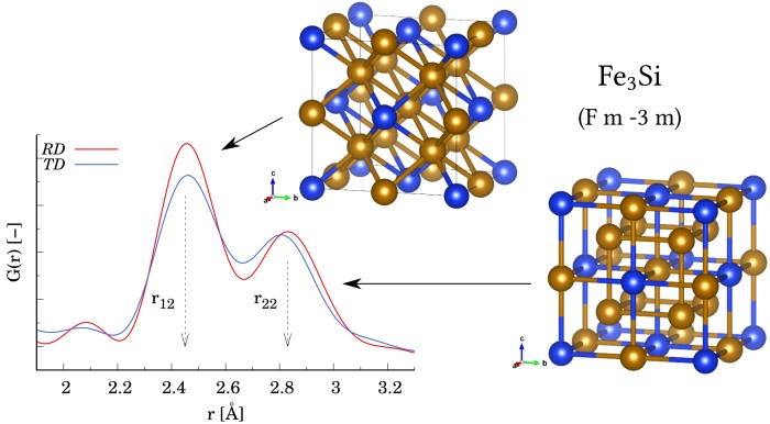
Fig. 1 The first coordination shell as seen by pair distribution function $G(r)$ measured along tensile (rolling) and transversal direction, RD and TD, respectively. Well-resolved sub-shells located at $r_{12}$ and $r_{22}$ refer to bond length distributions centered around 0.245 and 0.283 nm, respectively. These sub-shell peaks correspond to the nearest-neighbors environments of Fe$_{3}$Si cubic phase, as depicted in the figure. Fe and Si atoms are depicted with gold and blue colors, respectively.
Acknowledgements
Vitroperm-800 alloy in the form of thin ribbon was kindly provided by Dr. G. Herzer from VACUUMSCHMELZE GmbH Hanau, Germany. This research was financially supported by a Slovak Scientific Grant Agency VEGA (project No. VEGA 1/0638/24).
References
[1] H. Fukunaga, N. Furukawa, H. Tanaka, and M. Nakano, “Nanostructured soft magnetic material with low loss and low permeability,” Journal of Applied Physics, vol. 87, no. 9. AIP Publishing, pp. 7103–7105, May 01, 2000. doi: 10.1063/1.372944.
[2] G. Herzer, V. Budinsky, and C. Polak, “Magnetic properties of nanocrystalline FeCuNbSiB with huge creep induced anisotropy,” Journal of Physics: Conference Series, vol. 266. IOP Publishing, p. 012010, Jan. 01, 2011. doi: 10.1088/1742-6596/266/1/012010.
[3] M. Ohnuma, K. Hono, T. Yanai, M. Nakano, H. Fukunaga, and Y. Yoshizawa, “Origin of the magnetic anisotropy induced by stress annealing in Fe-based nanocrystalline alloy,” Applied Physics Letters, vol. 86, no. 15. AIP Publishing, Apr. 08, 2005. doi: 10.1063/1.1901807.
[4] D. Yudina, M. Marsilius, and J. Bednarcik, “Structural aspects of stress-induced magnetic anisotropy in Fe-based nanocrystalline alloy,” Journal of Alloys and Compounds, vol. 960. Elsevier BV, p. 171011, Oct. 2023. doi: 10.1016/j.jallcom.2023.171011.Speaker: Dr Jozef Bednarčík (Pavol Jozef Šafárik University in Košice, Faculty of Science, Institute of Physics) -
15:15
From Košice to the Orbit. A Successful Story of Applied Magnetism 30m
Presented article briefly explain the history and the success of applied magnetism, that has been the main focus of research and development scientist group originally seated at Slovak Air Force Academy of Milan Rastislav Štefánik in Košice. The group was focused on measuring of magnetic field since 1982 when they develop the first digital magnetometer in former Czechoslovakia.
Knowledge gathered during development of magnetometer and its further use for research activities led into wide industrial application of magnetism after 1990. The industrial version of magnetometer has been developed for mining and steel production industry. The scope of research has been spread again and topics as non-destructive diagnostics of machines, non-destructive archaeological prospection or magnetic navigation has been successfully solved.
In 2014 the skCUBE project was started and development of the first Slovak satellite began. Most of the knowledge in the field of applied magnetism has been used in development of magnetic actuators and calibration method for onboard magnetometer. Success of this work lead into cooperation on following satellite mission GRBAlpha. Nowadays, the research is continuing in the project consortium focused on the scaling of the magnetic actuator for satellites in weight category from 70 to 500 kg.
The article explains the results of development of satellite actuators. Laboratory measurements show that the efficiency of actuator is almost doubled in respect to the standard commercial products in CubeSat category. Based on this research the actuator can provide higher performance within the same volume, weight and input power, or provide the same performance and save volume, weight and input power.
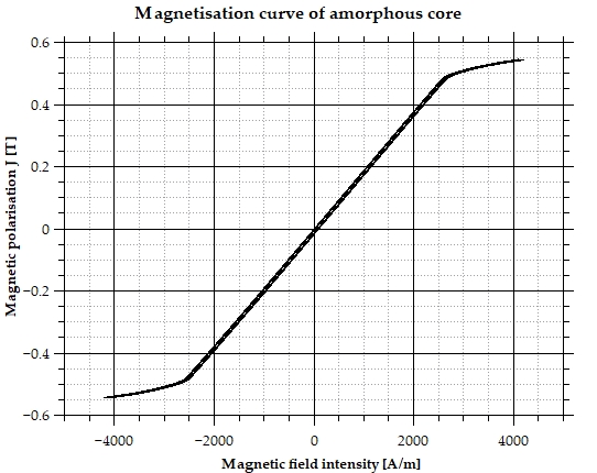
Fig. 1 Magnetisation curve of satellite actuator core optimized for minimal coercivity and maximal linearity.
Speaker: Dr Miroslav Šmelko (EDIS vvd.)
-
14:00
-
15:45
→
16:00
Coffe Break 15m MINERVA
MINERVA
Doktora Kostlivého 576/1 -
16:00
→
18:00
POSTER: Session 2 MINERVA
MINERVA
Doktora Kostlivého 576/1Convener: Jeffrey McCord (Kiel University)-
16:00
AC Current Sensor based on ME Composites Transducers: Resonance Damping, Current Dynamic and Electrostatic Disturbances 2h
The magnetoelectric (ME) effect is promising and has been studied for several applications: magnetic sensors [1], current sensors [2], energy harvesting [3] and wireless energy transmission. The extrinsic ME effect is preferred to the intrinsic one for these applications, requiring a magnetostrictive material mechanically coupled to a piezoelectric material. Current sensors based on extrinsic magnetoelectric effect have great potential with strong sensibilities, low cost, and easy fabrication. There are few studies on this kind of sensor, and they are mainly oriented toward the obtention of a great ME effect in ideal conditions [4] (lab environment, 50Hz sinus signal without electrostatic perturbation).
The current sensor presented here is obtained by inserting a trilayer Ni/PZT/Ni ME sample in a toric flux concentrator associated with permanent magnets to apply the required DC bias to obtain the best ME response. Nickel's 150 µm thickness layers are electrodeposited on a PZT square with a 4x5mm² surface and 0.5mm thickness. An amplifier with a bandwidth from 20Hz to 20kHz and a maximum current of 25 A is used for the tests. A winding of 24 turns is made around the toric flux concentrator to obtain a maximum current equivalent to 600 A.turns. The current dynamic is studied, and a 300 A.turns dynamic can be obtained if, for example, a maximum THD of 3$\%$ is required. This sensor aims at power electronics applications. Thus, it requires studying the sensor response to specific current waveforms that could excite mechanical resonances and thus disturb the measure. When a square current of 1 kHz is applied, these resonance frequencies are excited, impacting the sensor bandwidth. A mechanical dampening is proposed to limit this impact, using polyurethane mixed with tungsten powder to coat the ME sample. The results are encouraging because the resonance amplitude is reduced by a factor of 6, improving the sensor's bandwidth. In power electronics applications, the sensor will be subjected to electrostatic disturbances, and it is necessary to study its immunity toward them. Thus, the sensor is tested in an electrical field-controlled environment. An electronic based-on-charge preamplifier connected in differential mode strongly reduces these disturbances.
References
[1] S. Dong, J. Zhai, J. Li, and D. Viehland, “Small dc magnetic field response of magnetoelectric laminate composites,” Applied Physics Letters, vol. 88, no. 8. AIP Publishing, Feb. 20, 2006. doi: 10.1063/1.2178582.
[2] X. Yu, G. Lou, H. Chen, C. Wen, and S. Lu, “A Slice-Type Magnetoelectric Laminated Current Sensor,” IEEE Sensors Journal, vol. 15, no. 10. Institute of Electrical and Electronics Engineers (IEEE), pp. 5839–5850, Oct. 2015. doi: 10.1109/jsen.2015.2451551.
[3] Y. Zhou, D. J. Apo, and S. Priya, “Dual-phase self-biased magnetoelectric energy harvester,” Applied Physics Letters, vol. 103, no. 19. AIP Publishing, Nov. 04, 2013. doi: 10.1063/1.4829151.
[4] J. Zhang, P. Li, Y. Wen, W. He, A. Yang, and C. Lu, “Packaged current-sensing device with self-biased magnetoelectric laminate for low-frequency weak-current detection,” Smart Materials and Structures, vol. 23, no. 9. IOP Publishing, p. 095028, Aug. 14, 2014. doi: 10.1088/0964-1726/23/9/095028.Speaker: Mr Raphaël Filâtre (SATIE CNRS UMR 8029, ENS Paris-Saclay, 91190 Gif sur Yvette, France) -
16:00
Analysis of PHMR Sensor Characteristics Affected by Applied Current and Measurement Direction using Multi-Electrode Switch System 2h
Recently, magnetic sensors are being used in various applications such as autonomous vehicles and IoT. For the application of such magnetic sensors, the consistent performance of sensors is important. In particular, Planar Hall Magneto Resistance (PHMR) sensors have high signal sensitivity and low offset characteristics. However, it shows indiscriminately different offset characteristics during the sensor manufacturing stage. This study investigated the characteristics of the offset voltage and the phase of the characteristic curve in a NIFe/IrMn bilayer structure PHMR sensor, which vary depending on the direction of current application and voltage measurement. By applying an analytical method, we separated the sensor signal to classify the offset voltage characteristics unrelated to magnetoresistance and offset voltage characteristics caused by changes in the magnetoresistance phase. We also analyzed the ratio between signals with AMR characteristics and signals with PHMR characteristics affected by phase changes, as well as changes in sensitivity characteristics of the magnetic sensor. As a result, when the current application direction and voltage measurement direction were adjusted to specific conditions, the output voltage and sensitivity increased. These findings are expected to have implications for optimizing sensor design and manufacturing processes and improving sensor performance.

Fig. 1 A multi-electrode PHMR sensor consisting of 16 electrodes was used to control the directions of the applied current and the measured voltage according to the electrode setting using a switching system to check the sensor characteristics affected by the current distribution area, density and direction, and voltage measurement direction.
Acknowledgements
This paper is funded by the government (Ministry of Trade, Industry and Energy) in 2023. This study was conducted with the support of the National Institute of Industrial Technology Evaluation and Management.
References
[1] H. Gu, X. Zhang, H. Wei, Y. Huang, S. Wei, and Z. Guo, “An overview of the magnetoresistance phenomenon in molecular systems,” Chemical Society Reviews, vol. 42, no. 13. Royal Society of Chemistry (RSC), p. 5907, 2013. doi: 10.1039/c3cs60074b.
Speaker: Sunghyeok Lee -
16:00
Anisotropic Magnetocaloric Properties of Heusler Microwire Ni53Fe20Ga27 for Low and High Magnetic Field Change 2h
Magnetic refrigeration is a non-conventional cooling method providing environmentally friendly and more efficient cooling. One of the main advantages of magnetocaloric cooling is the scalability of the used material to the required application. On the other hand, decreasing the size will naturally cause a reduction of cooling power which may be solved by using higher magnetic field changes. Such a solution brings even more disadvantages – high energy consumption. In this work, we would like to present different methods how to deal with high energy consumption employing shape anisotropy of the microwire sample. Microwire’s fabrication process immediately provides strong shape anisotropy of the material with an easy magnetisation axis in the microwire's axis and a hard magnetisation axis perpendicular to the microwire. Indirect magnetic measurements were employed to study the magnetocaloric effect of Heusler glass-coated microwire Ni$_{53}$Fe$_{20}$Ga$_{27}$. The rotation of the sample does not have a significant influence on the magnetocaloric effect in high magnetic field changes. However, observed behaviour in low magnetic field changes opens new possibilities on how to utilise magnetocaloric cooling in real applications, since the magnetocaloric effect measured in the hard axis is negligible compared to the magnetocaloric effect of the sample placed in parallel with the applied magnetic field. This opens the possibility of using the sample's rotation in a low static magnetic field for cooling.
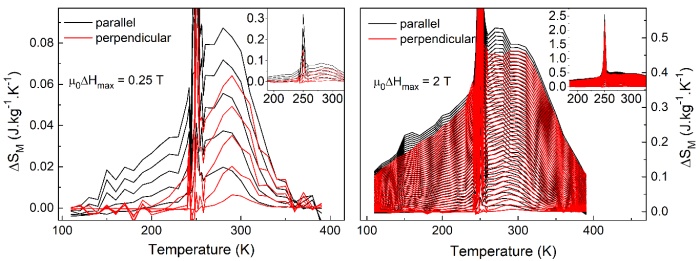
Fig. 1 Comparison of magnetocaloric effect in low (left) and high (right) magnetic field change for studied microwire in parallel and perpendicular position with respect to the applied magnetic field.
Acknowledgements
This work was supported by the projects APVV-16-0079 and VEGA 1/0180/23 and vvgs-2024-3079.
References
[1] M. Hennel, L. Galdun, A. Džubinská et al. “High efficiency direct magnetocaloric effect in Heusler Ni2MnGa microwire at low magnetic fields,” Journal of Alloys and Compounds, vol. 960, 170621, 2023. doi: 10.1016/j.jallcom.2023.170621.
[2] M. Orendáč, S. Gabáni, E. Gažo et al. “Rotating magnetocaloric effect and unusual magnetic features in metallic strongly anisotropic geometrically frustrated TmB4,” Scientific Reports, vol. 8, 10933, 2018. doi: 10.1038/s41598-018-29399-2.Speaker: Miroslav Hennel (CPM, TIP UPJS) -
16:00
Assessment of Magnetomechanical Symptoms Caused Near Yield Area for the Purpose of Material Stress Evaluation 2h
Many materials and machines that may pose a real risk of catastrophe due to fatigue wear, exceeding stress limits or the appearance of plastic deformation are magnetic. In addition, there is a constant trend indicating the need to develop methods towards the technology of detecting early stages of damage, which is possible thanks to the use of magnetic methods [1]. However, due to the variety and complexity of the magnetomechanical effects, it is difficult to identify quantitative measures that can precisely define diagnostic thresholds for specific magnetic signals.
Both quantitative and qualitative changes of the object magnetization status are coupled with thermal, electrical and mechanical effects in the structure. Complex, multiparametric non-linear relations between chemical composition, physical structure, stresses and magnetization of the material can be observed under test. Required for analysis and interpretation of such multiple interrelations and non-linear actions, are suitable models which would highlight the most effective reactions (phenomena). Therefore, the publication analyzed near yield area in construction steel on the behavior of magnetomechanical phenomena. For this purpose, the test stand was built, that is able to analyze the magnetic characteristics of samples that are simultaneously subjected to tensile stresses. The specimens were stretched with full control on strain in the material. In the experiment a customized measurement device (MagMouse) which consisted of a matrix of three-axis magnetoresistive sensors was used.

Fig. 1 Diagram of the test stand for the experiment.
The obtained results indicate new possibilities of describing and modeling phenomena that better describe the observed reality. Along with the new description of physical interactions, new methods of measuring and analyzing the magnetic signal were presented, both in terms of elastic and plastic loads. In both cases, changes in the mechanical properties of the material, taking into account near yield area of the steel, result in changes in the magnetic properties, mainly magnetization and magnetic permeability of the material. The results of the research indicates tips on how to conduct the experiment, considering rolling direction of steel, to find diagnostic information.
References
[1] A. Daem, P. Sergeant, L. Dupré, S. Chaudhuri, V. Bliznuk, and L. Kestens, “Magnetic Properties of Silicon Steel after Plastic Deformation,” Materials, vol. 13, no. 19. MDPI AG, p. 4361, Sep. 30, 2020. doi: 10.3390/ma13194361.
Speaker: Szymon Gontarz (Warsaw University of Technology, Faculty of Automotive and Construction Machinery Engineering) -
16:00
Contactless Sensors in Automotive 2h
This study is dedicated to the theoretical investigation and practical application of amorphous glass-coated microwires as pressure sensors in the automotive industry. These materials, characterized by a non-crystalline structure, offer a wide range of unique properties, making them attractive for numerous technological applications, including use in sensory systems.
Based on experimental measurements and analyses, amorphous glass-coated microwires have proven to be effective and reliable solutions for pressure measurement in automotive systems. In this study, we demonstrate the dependency signal of glass-coated microwires on the changing pressure inside the braking hose. The findings of this work, including the monotonic dependency (Fig. 1) of the pressure sensor on the amorphous glass-coated microwire, open new perspectives for the use of amorphous microwires in the field of pressure sensing and their sensor applications in various industrial sectors.
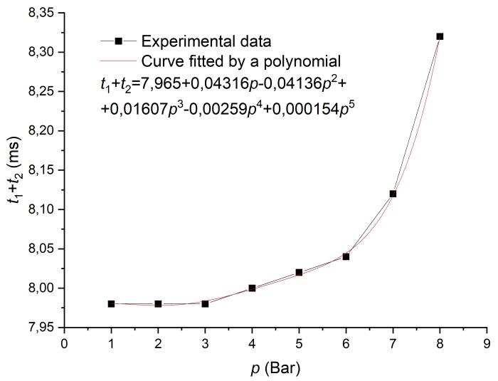
Fig. 1 Dependence of $t_1+t_2$ on pressure change.
Speaker: Samuel Onufer -
16:00
Dynamics of a Single Domain Wall Driven by an Alternating Magnetic Field in Bistable Microwire 2h
A new experiment (Fig. 1) is presented for studying the dynamics of a single domain wall (DW) driven by an alternating magnetic field. The bistable cylindrical glass-coated microwire is placed in a system of four coaxial coils. One pair of coils in Helmholtz geometry (HC) in parallel combination allows the whole wire to be axially magnetized. This pair of coils in antiparallel combination provides the possibility of creating a single DW in the place of the local zero field. As long as this magnetic field remains active, the created DW is located in an artificial potential well. The alternating sinusoidal magnetic (AC) field with angular frequency $\Omega$ generated by the magnetizing coil (MC) causes DW to start oscillating. The voltage induced due to the wall oscillation is measured through the pick-up coil (PuC) connected to the lock-in amplifier (LI). The parameters of the entire system of coils were optimized in order to prevent the possible influence of resonance effects in the range of measured frequencies. Using this experimental set-up, two types of measurement of the induced voltage can be performed: firstly as a function of the angular frequency (in the frequency range from 30 kHz to 600 kHz), and secondly as a function of the amplitude of the alternating field. These measurements were carried out without the wire and with the wire in the coil system in two cases, first without a DW and then with a single DW in the wire. The dependences without wire and with wire but without DW were identical, which made it possible to obtain a signal from the DW oscillation alone.
Analysis of the measured dependences of the induced voltage versus AC magnetic field amplitude revealed the amplitudes of the critical current when the DW left the region inside the pick-up coil for various frequencies. We then performed measurements without an artificial potential well in order to verify the validity of the DW oscillation model in a local potential well. Based on the measured results, it seems that this model does not describe the observed behaviour correctly. This is probably due to excessive DW axial length.
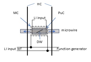
Fig. 1 Experimental set-up.Acknowledgement
This research was supported by VEGA Grant No. 1/0350/24 from the Scientific Grant Agency of the Ministry for Education of the Slovak Republic, and project No. 019/2019/1.1.3/OPVaI/DP (ITMS code 313011T557).
Speaker: Dr Jozef Onufer (Department of Physics, Faculty of Electrical Engineering and Informatics, Technical University of Košice) -
16:00
Fabrication and Application of Magnetic-Based Shear Force Sensor 2h
The shear force sensor developed in this study has pressure insensitivity, high sensitivity, and bi-directional measurements, and it was fabricated on a flexible substrate. This sensor was fabricated by applying a polymer based pillar structure to the Planar Hall Magnetoresistance (PHMR) sensing element. The column structure was placed on the PHMR sensing element to minimize the effect of normal force and improve the sensor's ability to detect shear force. Signal monitoring has been simplified to enable precise and accurate measurements. The sensitivity of this sensor is 500 times greater than its normal force sensitivity, providing evidence of accurate shear force measurements. The sensor exhibits non-hysteretic behavior and excellent repeatability, confirming its reliability and stability. By utilizing the sensor's characteristics for shear force measurement, we demonstrate its suitability for practical experiments such as flow velocity measurement and Braille recognition. The shear force sensor that consistently perform well in various environments show potential for fields such as AI robots, wearable devices, and medical equipment that require precise control and sensing.
Acknowledgements
The authors acknowledge funding from the National Research Foundation of Korea (NRF) grant funded by the Korean government (MSIT) (Grant No. NRF-2018R1A5A1025511) and in part by the R&D program of MOTIE (Grant No. 20011264).
References
[1] M. Kim et al., “Pressure-insensitive magnetic shear force sensor with pillar structure for versatile application,” Applied Materials Today, vol. 36. Elsevier BV, p. 102076, Feb. 2024. doi: 10.1016/j.apmt.2024.102076.
[2] J. Lee et al., “Bridge Resistance Compensation for Noise Reduction in a Self-Balanced PHMR Sensor,” Sensors, vol. 21, no. 11. MDPI AG, p. 3585, May 21, 2021. doi: 10.3390/s21113585.
[3] Z. Ji, H. Zhu, H. Liu, T. Chen, and L. Sun, “A flexible capacitive tactile sensor for robot skin,” 2016 International Conference on Advanced Robotics and Mechatronics (ICARM). IEEE, Aug. 2016. doi: 10.1109/icarm.2016.7606920.Speaker: Hyeji Kim (Daegu Gyeongbuk Institute of Science & Technology) -
16:00
High Accuracy Vehicle Speed Estimation Using Dual-Axis Magneto-Impedance Sensors 2h
With the rapid development of automated driving, real-time vehicle speed estimation can assist in monitoring road traffic condition and predicting change in traffic volume. Direct transmission of detected traffic information to vehicles in real-time is referred to as Vehicle-to-Infrastructure (V2I) communication, which is essential in automated driving. Magnetic sensor technology, due to its low cost, compact size, strong anti-interference capability, and absence of privacy concerns, is being utilized in new-generation vehicle detection [1]. The prevailing method for speed estimation mainly relies on the time difference between data from at least two sets of sensors as a reference. The simplest instantaneous speed calculation model can be summarized as $v=l/\Delta t$, where $l$ is the distance between sensors, and the $\Delta t$ is time difference of the maximums of two waveforms.
In this study, we utilized 2-axis Magneto-Impedance (MI) sensors for estimate vehicle speed [2]. We placed MI sensors on the side of the road to reduce the interference of vehicle body. An analysis of issues causing a decrease in accuracy has been conducted as shown in Fig.1. Due to interference caused by the structure of the vehicle, the maximum value of the waveform may shift, leading to significant errors in speed calculation. We proposed bandpass filter (0.1-50 Hz) and moving average ($n$=1500) to filter the noise. The dashed line represents the waveform smoothed by a moving average with $n$=1500, where it can be observed that deviations caused by noise are eliminated, enabling more precise calculation of instantaneous speed. This method achieved 97 $\%$ average accuracy in speed estimation ($\pm$ 3 km/h) with sensor spacing of 1.6 m. Additionally, we proposed a speed estimation method based on frequency domain features, validating the feasibility of speed estimation with a single sensor.
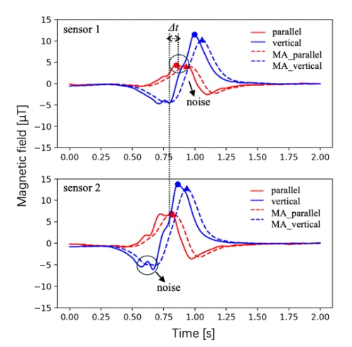
Fig. 1 Using the maximum value differential method for speed estimation.
References
[1] S. -L. Jeng, W. -H. Chieng and H. -P. Lu, "Estimating Speed Using a Side-Looking Single-Radar Vehicle Detector," in IEEE Transactions on Intelligent Transportation Systems, vol. 15, no. 2, pp. 607-614, April 2014, doi: 10.1109/TITS.2013.2283528.
[2] R. Yao and T. Uchiyama, "Analysis of Magnetic Signatures for Vehicle Detection Using Dual-Axis Magneto-Impedance Sensors," in IEEE Sensors Journal, vol. 24, no. 6, pp. 8721-8730, March 15, 2024, doi: 10.1109/JSEN.2024.3357852.Speaker: Ruixuan Yao (Department of Electronics, Graduate School of Engineering, Nagoya University, Nagoya, Japan) -
16:00
Improved Method for Linear Position Sensing through Conductive Wall 2h
Our group has experimented in the past with development of contactless position sensors suitable for retrofitting to pneumatic actuators - i.e. piston position sensing [1,2]. The proposed advantage was AC-operation enabling use of synchronous detection and suppression of noise (including DC). Excitation at low frequency (<100 Hz) made possible measurement through aluminum sheath (piston barrel) without internal permanent magnet fixed to movable piston. An array of external fluxgate magnetometers (Texas Instruments DRV425) monitors the response to excitation from internal metallic target (aluminum piston and ferrous piston rod).
While results with axial-excitation model were promising [2], the radial-excitation design achieved only moderate level of accuracy [1]. The approach published in [1] utilized simple position estimation options: i) finding the sensor with maximum signal or ii) calculation of weighted average from two sensors with strongest signal or iii) least-square fitting to known response function of single magnetometer. The reported position errors were $\pm$15 mm, $\pm$5 mm and $\pm$2 mm, respectively [1].
However, with modified data processing approach, improved positioning results are achievable. For illustration, data from only three sensors in the larger array are shown here. With variable piston position z, the raw magnetic field data are shown in Fig.1a and the corresponding gradients (differences from magnetometer pairs 30 mm apart) in Fig.1b.

Fig. 1 Three channels of raw data (a) and corresponding gradients (b) with “linear” parts.
The gradient curves are piecewise monotonic and approximately linear near zero-crossing. Within each segment of array, the appropriate pair of sensors is selected as source of signal based on the relative signal strength (amplitude). The gradient can then be recalculated into position estimation. Achieved position error level was $\pm$1 mm using polynomial approximation of 3rd order. Early results indicate potential for further improvement. More improvement could possibly be achieved with additional processing of another (perpendicular) component of measured response field.
Acknowledgements
This work was supported by GACR project 24-12705S Novel Magnetic Position Sensor.
References
[1] J. Vyhnanek, P. Ripka, and A. Chirtsov, “Linear Position Sensing through Conductive Wall without Permanent Magnet,” Proceedings of Eurosensors 2017, Paris, France, 3–6 September 2017. MDPI, Aug. 08, 2017. doi: 10.3390/proceedings1040390.
[2] P. Ripka, A. Chirtsov, and V. Grim, “Contactless Piston Position Transducer With Axial Excitation,” IEEE Transactions on Magnetics, vol. 53, no. 11. Institute of Electrical and Electronics Engineers (IEEE), pp. 1–4, Nov. 2017. doi: 10.1109/tmag.2017.2715073.Speaker: Mr Antonin Platil (Czech Technical University in Prague, Faculty of Electrical Engineering) -
16:00
Linear Position Sensor using Magnetically Bistable Microwire 2h
This study explores developing and applying a linear position sensor leveraging bistable microwire technology. Bistable microwires offer a unique advantage in sensor design because they can detect multiple physical quantities with high sensitivity through simple electronic configurations. It is even possible to separate the external magnetic field’s contribution, which opens up the opportunity to measure in various magnetic environments.
Using all the advantages of bistable microwire, it is possible to design a linear position sensor with high resolution. The core of this measurement system relies on the bistable microwire, excited by an alternating magnetic field generated by an excitation coil. The microwire response signal is subsequently captured by a sensing coil, which is processed by an STM32 microcontroller.
With the presented unique approach, it is possible to transfer the linear position of the piston into the switching time and obtain high sensitivity down to 1 $\mu$m, representing a very high resolution. Additionally, it was found that the device is resistant to temperature effects, giving it an advantage over other linear displacement sensors.

Fig. 1 Theoretical current and magnetic field strength characterization depends on the distance (left), and the real characteristic of the switching time depends on the distance (right).
Acknowledgements
This work was partially supported by Slovak Grant Agencies VEGA 1/0053/19 and APVV-16-0079.
References
[1] P. Jacko, R. Jurč, L. Galdun, Ľ. Hvizdoš, D. Kováč, and R. Varga, “Linear position sensor using magnetically bistable microwire,” Sensors and Actuators A: Physical, vol. 349. Elsevier BV, p. 114017, Jan. 2023. doi: 10.1016/j.sna.2022.114017.
Speaker: Patrik Jacko -
16:00
Linear Position Sensor with Extended Linearity Range 2h
The position sensors are widely used in various industrial applications. The sensors with linear variable differential transformer (LVDT) configuration are the most common position transducers because of their cost-effective and simple structure and straightforward operation. LVDT position sensors are used in robotics, automation, manufacturing and machining processes, automatic valves, and the automotive and aviation industries.
Conventional LVDT position sensors have cylindrical structure with solenoidal coils and moving part and the moving part or armature is a ferromagnetic cylinder. However, the cylindrical LVDT sensors cannot be used for applications, where the armature and the coils must be physically separated. Flat-tape LVDT position sensors [1,2] are alternatives to the cylindrical LVDT sensors, which have more mechanical feasibility for the position measurement. However, achieving high linearity in flat-type position sensors is more challenging.
A novel structure of flat-type position sensors is presented in this paper. Fig. 1 presents the magnetic flux distribution in the 2D model of the proposed position sensor. The sensor has a long excitation coil, and two differentially connected pickup coils wound around a long-length cuboid Ferrite core. The armature is a short-length cuboid Ferrite core. The pickup coils are optimized to enhance the linearity range of the LVDT position sensor. 2D and 3D finite element methods (FEM) are utilized for the design optimization of the position sensor. Finally, detailed measurements are conducted to evaluate the linearity improvement in the optimized flat-type position sensor.
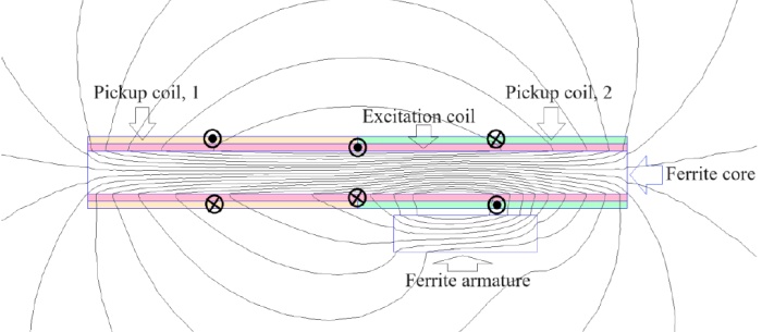
Fig. 1 Magnetic flux distribution in the 2D model of the linear position sensor.
Acknowledgements
This work was supported by GACR project 24-12705S Novel Magnetic Position Sensor.
References
[1] Y. Kano, S. Hasebe, and H. Miyaji, “New linear variable differential transformer with square coils,” IEEE Transactions on Magnetics, vol. 26, no. 5. Institute of Electrical and Electronics Engineers (IEEE), pp. 2020–2022, 1990. doi: 10.1109/20.104605.
[2] M. Mirzaei, J. Machac, P. Ripka, A. Chirtsov, J. Vyhnanek, and V. Grim, “Design of a flat‐type magnetic position sensor using a finite‐difference method,” IET Science, Measurement & Technology, vol. 14, no. 5. Institution of Engineering and Technology (IET), pp. 514–524, Jul. 2020. doi: 10.1049/iet-smt.2019.0197.Speaker: Prof. Pavel Ripka (Czech Technical University) -
16:00
Magnetic Sensors for Magnetic Communication: a Comparison between GMI and Induction-based Sensors 2h
With the increasing communication needs in harsh environment such as underground, submarine or biological tissues where communications methods with radiofrequency (RF) waves are very difficult, the magnetic communication methods, in which the message is transmitted via the magnetic field, are drawing more and more attention. The advantage is the ability of magnetic field to penetrate all non-magnetic materials.
In a magnetic communication system, a sensor is placed in the receiver side to capture the modulated magnetic signal from the transmitter. In a conventional system, the used sensors (coil) are based on the magnet induction principle (Fig.1a) [1]. However, the sensitivity of this type of sensor decreases when the working frequency is relatively low (typically a few tens of kilohertz) and when the size of the coil decreases (in mobile applications). In these conditions, it is relevant to consider other types of magnetic sensors for these communication systems. In this paper, we investigate the possibility of using a Giant Magneto-Impedance (GMI) sensor for magnetic communication (Fig.1b).
Fig. 1 Communication system with induction-based receiver and GMI based receiver.
The main objective of this work is to compare the sensitivity of this GMI sensor and the conventional coil according to several considerations such as the working frequency and the size of the coil. The underlying idea is to determine the conditions under which the use of the GMI sensor exhibits advantage. This comparison is based on the calculation and the measurement of the intrinsic sensitivities of both sensors.
The sensitivity of a coil is a function of a variety of parameters including its radium $r$, the working frequency $f$ and the number $n$ of turns of the coil, etc. Assuming that the receiving coil is “relatively small”, the sensitivity can be expressed as:$S_{coil}$=$2nf$$\pi^2$ $r^2$
Meanwhile the sensitivity of a given GMI sensor could be considered as independent of the frequency (until some limit defined by the electronic conditioning and the frequency of the excitation of the GMI element). If we fix two parameters among the three parameters ($n$, $f$, $r$) of the coil, it possible to calculate the upper (or lower) limit for the third parameter beyond which a GMI sensor exhibits better sensitivity. For example, this kind of calculation shows that a coil with $n$ =10 turns and a working frequency $f$ = 60 kHz will be less sensitive than a typical high sensitivity GMI sensor (with sensitivity of about 700 kV/T) when the radius of the coil is smaller than 24 cm.
The equivalent magnetic noise expressed in $T/\sqrt{Hz}$ is another important quantity to be compared. It determines the smallest magnetic field that sensors could measure by multiplying it with the square root of the bandwidth. This smallest field will define the maximum communication range that could be achieved. These comparisons aspects will be detailed in the full paper.
References
[1] J. -Y. Kim, H. J. Lee, J. -H. Lee, J. H. Oh and I. -K. Cho, "Experimental Assessment of a Magnetic Induction-Based Receiver for Magnetic Communication," in IEEE Access, vol. 10, pp. 110076-110087, 2022, doi: 10.1109/ACCESS.2022.3214507.
Speaker: Miao XU (Univ. Grenoble Alpes, CNRS, Grenoble INP, G2Elab) -
16:00
New Steel Stress Coupons for Steel Health Monitoring 2h
The development of steel stress coupons, including an amount of residual stresses up to the yield point has been proven useful for the development of the Magnetic Stress Calibration (MASC) Curves [1]. These coupons were developed by autogenous welding in different types of steels in order to compare surface and bulk residual stresses determined by X-ray diffraction in the Bragg – Brentano set-up and nuclear diffraction respectively with magnetic properties in the same volume and direction. A new principle of developing new steel stress coupons is presented in this paper, related to the induction heating and consequent water or oil quenching of the heated steel, keeping the steel coupon pressed to avoid stress-induced bending. This way the residual stress profile includes similar maxima and minima, corresponding to stresses approaching the yield point. The advantage of these new coupons is the ease of manufacturing and the fact that phase transformations are less than for the case of welding. The technology is repeatable, thus allowing for successful interlaboratory tests.
References
[1] P. Vourna, E. Hristoforou, A. Ktena, P. Svec, and E. Mangiorou, “Dependence of Magnetic Permeability on Residual Stresses in Welded Steels,” IEEE Transactions on Magnetics, vol. 53, no. 4. Institute of Electrical and Electronics Engineers (IEEE), pp. 1–4, Apr. 2017. doi: 10.1109/tmag.2016.2628025.
Speaker: Prof. Evangelos Hristoforou (Sensors Lab, National TU of Athens) -
16:00
Novel Fluxgate Sensor Incorporating Twisted Glass-Coated Microwires 2h
Fluxgate sensors exhibit the highest sensitivity among the magnetic sensors for detecting d.c. or low frequency a.c. magnetic fields in the $\mu$T range and below. Typically, in a basic fluxgate sensor, the information about the magnetic field is extracted from either the amplitude of the induced signal or the higher-order harmonics of the excitation signal. Another alternative is to extract the field information from the residence times difference (RTD) of the induced signal peaks. However, to achieve well-defined sharp peaks in the induced signal, it is essential for the core material to possess both high magnetic permeability and fast magnetic switching capabilities. Among such materials, glass-coated microwires exhibiting large Barkhausen effect are promising for the advancement of RTD sensors. Recently, a novel technique for switching the axial magnetization in bistable glass-coated microwires has been introduced [1]: a current passing through a magnetic microwire under controlled torsion.
In this work, we present the development of the new RTD magnetic sensor, which eliminates the need for an excitation coil. The sensor consists of a soft magnetic glass-coated microwire surrounded by a pick-up coil, and an electronic system with multiple roles: to generate the excitation signal, to process the pick-up signal and to display the measured results. The sensor output signals for 3 representative categories of glass coated microwires – positive magnetostrictive amorphous Fe$_{77.5}$Si$_{7.5}$B$_{15}$, low positive magnetostrictive nanocrystalline Fe$_{73.5}$Si$_{13.5}$B$_{9}$Cu$_{1}$Nb$_{3}$, and nearly zero magnetostrictive amorphous Co$_{68.18}$Fe$_{4.32}$Si$_{12.5}$B$_{15}$ - used as sensitive elements are presented in Fig. 1. Our experiments demonstrate that annealed Co-based glass-coated microwires fluxgate sensor exhibits improved linearity in the transfer function and lower noise levels compared with Fe-based ones.
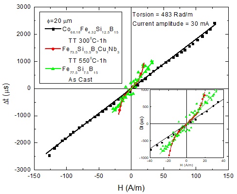
Fig. 1 The RTD sensor transfer curves measured for microwires with $\Phi$ = 20 $\mu$m and different compositions.
This sensor holds potential for applications across various domains, including digital compasses, parking sensors, magnetometers, and other detection systems that integrate magnetic sensors. Its compact design and enhanced performance make it a valuable addition to the field of magnetic sensing technology.
Acknowledgements
Financial support from the MCID Nucleu (PN 23 11 01 01 – Contract #18N/2023) Program is highly acknowledged.
References
[1] S. Corodeanu, H. Chiriac, A. Damian, N. Lupu, T.-A. Óvári, “Field and current controlled domain wall propagation in twisted glass-coated magnetic microwires”, Scientific Reports, vol. 9, article no. 5868, Apr. 2019. https://doi.org/10.1038/s41598-019-42352-1.
Speaker: Nicoleta Lupu (National Institute of Research and Development for Technical Physics, Iasi, Romania) -
16:00
Novel Power Saving Algorithm for AMR Magnetometer with Fast Settling Feedback Loop 2h
AMR magnetometers are used in many applications where low power consumption is desired, particularly in space applications [1] where it is one of crucial parameters. Although fluxgate/optically pumped magnetometers dominate space industry due to their ultralow-noise, AMRs are increasingly used if the roughly 100-fold increase of noise is not an issue, as they are miniature, lightweight, solid state and readily available (off-the-shelf). [2] In this work, we propose a novel method for reducing power consumption while maintaining good precision/low noise of the instrument. For the best precision and stability, AMR magnetometer almost always utilizes feedback compensation and so-called flipping (set/reset) technique. Both greatly increase power consumption. Flipping power consumption can be reduced by utilizing ultrashort pulses [2] generated by MOSFET H-bridge instead of traditional capacitor coupled half bridge. Closed loop magnetic field compensation leads to great improvement in linearity of magnetometer and its temperature stability of sensitivity. However, in many applications, measured magnetic field is steady and its variation is slow or with only occasional fast perturbations. The same applies also for temperature of magnetometer itself. In our contribution, we propose a method where we switch from open-loop operation into feedback (closed-loop) only when necessary. With a fast feedback-loop settling, power consumption can be greatly reduced: on tested magnetometer with HMC1021, compensation in closed loop requires approx. 100 mW for steadily compensating 50 $\mu$T field, but only 10 mJ per correction measurement. Proposed algorithm uses three input variables to decide if “calibration” measurement with closed loop is necessary - namely: change in temperature, change in magnetic field and time elapsed from last calibration. After closed-loop “calibration” is performed, open-loop measurement is used as an additional ΔB to the last closed loop absolute measurement. In Fig 1., a slowly rising magnetic field was applied, algorithm action can be seen as a correction (when $\Delta B$ > 1 $\mu$T). Impact on linearity of magnetometer using proposed algorithm can be seen in Fig 2. (where criterium for calibration is set to $\Delta B$ > 5 $\mu$T).
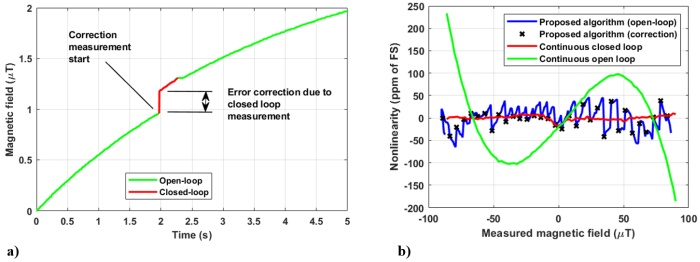
Fig. 1 a) Response of algorithm to rising magnetic field. b) Linearity comparison (algorithm, OL, CL).
Acknowledgements
This work was supported by the Grant Agency of the Czech Technical University in Prague, grant No. SGS22/170/OHK3/3T/13.
References
[1] M. Díaz-Michelena, “Small Magnetic Sensors for Space Applications,” Sensors, vol. 9, no. 4. MDPI AG, pp. 2271–2288, Mar. 30, 2009. doi: 10.3390/s90402271.
[2] Leitner et al., “Design of the Magnetoresistive Magnetometer for ESA’s SOSMAG Project,” IEEE Transactions on Magnetics, vol. 51, no. 1. Institute of Electrical and Electronics Engineers (IEEE), pp. 1–4, Jan. 2015. doi: 10.1109/tmag.2014.2358270.Speaker: David Novotný (Department of Measurement, Faculty of Electrical Engineering, Czech Technical University in Prague) -
16:00
Quality Monitoring of Glued Joints Using Bistable Microwires 2h
Today adhesive technology is of particular importance in different industrial sectors, for example in automotive industry or in aerospace technology [1]. In building industry adhesive technology is often used to avoid punctual transmissions of power. Glued glass elements in constructional engineering are only one example of application. However, the adhesive joint is subject of an ageing process affecting the quality and the durability of the adhesive joint. Therefore, an appropriate monitoring is essential in respect of adhesive joints. Micro wire sensors are miniaturized magnetic contactless sensors of physical quantities [2,3]. Micro wires are made of metallic alloy core and glass coating. Their size, high added value, robustness, simple production process and also their symmetry, glass-coating, possibility of contactless sensing leads to their utilization as a miniaturized sensor with a wide range of applications. Continuous monitoring that provides accurate data not only helps with identification of real-time material properties but also contributes to maintenance planning and reducing risk of future disasters. [3] The most important thing is that micro wires can provide measurements from inside of adhesive bond.
This work provides an analysis of the measurement of a bonded joint subjected to tensile loading. The investigation utilized an aluminum strip of EN AW 6060 as the test sample. The bonded joint was engineered with an overlap area measuring 20$\times$50 mm. Within this bonded interface, a 30 mm micro wire was embedded to facilitate the local monitoring of stress development within the adhesive layer. Two commercially available adhesives were employed for this study: Alteco Super Glue and Loctite Super Bond Power Gel.
The samples were subjected to tensile testing. During the testing, the magnetic response of the embedded micro wires was measured in relation to the applied tensile load. The experimental data revealed that high-quality bonded joints produce a monotonic magnetic response, indicating consistent stress distribution and adhesion integrity. In contrast, low-quality bonded joints exhibited a discontinuous magnetic response, which signifies irregular stress distribution and potential adhesion failures.
The results show that the magnetic microwires could be an effective tool for detecting the formation of defects within bonded joints. By identifying these defects early, it is possible to predict the subsequent failure of the joint. This methodology provides valuable insights into the reliability and durability of adhesive bonds, contributing to improved quality control in manufacturing processes involving bonded joints.
Acknowledgements
This work was partially supported by Slovak Grant Agencies VEGA 1/0180/23 and APVV-16-0079.
References
[1] S. Böhm, H. Thiede, T. Ummenhofer and E. Stammen, “ Damage detection and monitoring of glued elements in civil structures using adhesive layer integrated markers,” https://data.smar-conferences.org/SMAR_2011_Proceedings/papers/110.pdf
[2] A. Allue et al., “Smart composites with embedded magnetic microwire inclusions allowing non-contact stresses and temperature monitoring,“ Composites Part A: Applied Science and Manufacturing, Vol. 120, 2019, pp 12-20. doi: 10.1016/j.compositesa.2019.02.014.
[3] R. Jurc et al., “Sensoric application of glass-coated magnetic microwires in Magnetic Nano- and Microwires, Design, Synthesis, Properties and Applications.“ Woodhead Publishing Series in Electronic and Optical Materials 2020, Pages 833-868 doi: 10.1016/B978-0-08-102832-2.00028-1.Speaker: Miroslav Komorník (RVmagnetics, a.s.) -
16:00
Rotating Fluxgate Magnetometer for Precise Estimation of Fields Below 1nT 2h
In this contribution we present development of a device and means of establishing low magnetic fields (<1nT), such as a remanence in a magnetic shield. In a previous development [1], we used a rotating AMR magnetometer for establishing and maintaining near-zero field in a coil system, where rotation enables suppression of the inherent sensor offset and its drift without frequent recalibrations. However, the AMR system suffered from the elevated noise (>100 $\mathrm{pT/\sqrt{Hz}}$ @ 1 Hz), limiting its practical use for fields smaller than 1 nT. We thus decided to use the fundamental mode orthogonal fluxgate [2] (1 $\mathrm{pT/\sqrt{Hz}}$ @ 1 Hz) for the improved version of the device.
Left section of Fig. 1 shows the custom magnetometer with 24-bit ADC, $\pm$2 $\mu$T range and wireless data transfer. Board provides excitation and demodulation of a 60 mm long magnetic wire sensor with 2 $\mathrm{pT/\sqrt{Hz}}$ @ 1 Hz noise. The magnetometer is rotated along its axis at roughly 60 RPM using a rotational platform made out of non-magnetic components, an aluminum shaft and externally mounted stepper motor. The residual field amplitude and phase (direction in rotational plane) can be obtained either after secondary synchronous demodulation or sinusoidal fitting in post-processing.
We have surveyed the residual magnetic field in a one meter tall 6-layer permalloy magnetic shield. The low internal remanence is important not only for sensor calibrations but also for annealing of OFM sensors [2]. The vertical profile is seen in the middle section of Fig. 1. There are basically two spots of low field (<1nT) : at the height of 325 mm and below 100 mm from the bottom of the innermost layer. The higher position, however, has a disadvantage of rapid change of vector orientation.
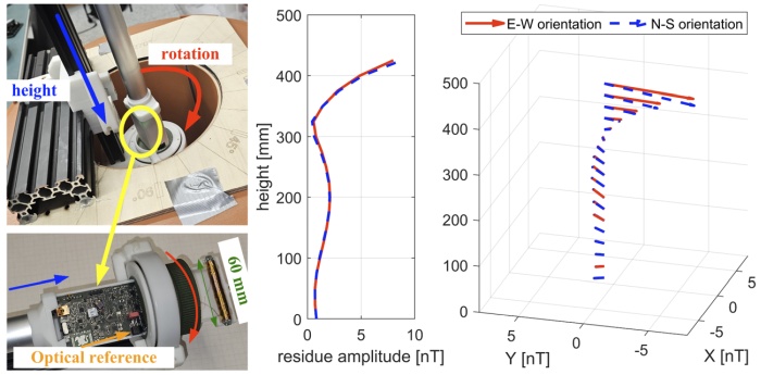
Fig. 1 (left) Magnetometer and rotation assembly. (right) Magnetic shielding residual field height profile and its 3D view for different orientation of the shielding in respect to Earth’s magnetic field.
Acknowledgements
This work was supported by the Grant Agency of the Czech Technical University in Prague, grant No. SGS22/171/OHK3/3T/13.
References
[1] M. Janosek, M. Dressler, and E. Saunderson, “Stabilized magnetic vacuum using a rotating fluxgate sensor,” 2020 IEEE SENSORS. IEEE, Oct. 25, 2020. doi: 10.1109/sensors47125.2020.9278793.
[2] M. Butta and B. P. Schutte, “Low-Noise Orthogonal Fluxgate Using Flipped Current Joule Annealing,” IEEE Transactions on Magnetics, vol. 55, no. 7. Institute of Electrical and Electronics Engineers (IEEE), pp. 1–6, Jul. 2019. doi: 10.1109/tmag.2019.2894302.Speaker: Michal Dressler (Czech Technical University in Prague, Faculty of Electrical Engineering) -
16:00
Specific Lock-in Amplifier for Fluxgate Sensor Testing 2h
Construction of a digital lock-in amplifier [1] specifically designed for fluxgate sensor testing is presented together with first results. The instrument is based on a low-noise, multi-stage, fully-differential, analog front-end (G = 0.1 - 100$\times$), followed by 1 MSa/s, 20-bit, SAR-ADC (LTC2378) for high dynamic range. All necessary digital signal processing is done within a Cyclone V FPGA. Excitation signal for the fluxgate sensor is derived internally as well as the reference signal for sine table read-out (using 25-100 sine-wave samples per period of the fluxgate output signal at 2$f_{exc}$). The instrument currently supports several fixed excitation frequencies in the range of $f_{exc}$ = 5 to 20 kHz and H-bridge amplitudes (5-15 V) for excitation current tuning. Digital multiplier output signal is filtered using FIR filter (900 taps, >100 dB attenuation at 5 kHz) and decimated to 10 kSa/s for further processing (averaged PSD calculation) in the computer. In order to allow complete closed loop testing of the fluxgate sensors the device is equipped with a 20-bit R2-R DAC (DAC11001A) driven voltage-to-current converter. The resolution of the DAC is enhanced to 26-bits by $\Delta\sum$ modulation technique (digital resolution increase from 125 pT to 2 pT for $\pm$65 $\mu$T Full Scale range). In closed feedback mode, the instrument essentially forms a single-axis digital magnetometer [2], but with an ability to adapt to many different sensor types due to variable excitation and amplification settings. First measurements indicate comparable noise results to measurements done with SR830 (3.5 $\mathrm{pT/\sqrt{Hz}}$ at 1 Hz for a race-track fluxgate sensor, 16 kHz $f_{exc}$). Fig.1 shows the noise-floor for different input amplifier settings (for fluxgate sensor excitation disconnected). At 1 Hz the noise floor was below the measured sensor noise even for the lowest amplification setting (0.1$\times$).
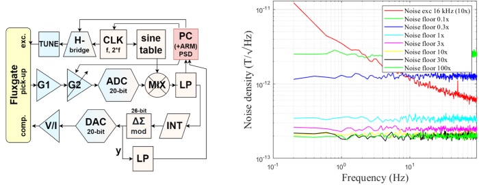
Fig. 1 Block diagram of the lock-in based test setup (left), measured race-track fluxgate sensor noise and noise-floor for several input amplifier gain options (right).
Acknowledgements
This work was supported by a SGS grant at CTU in Prague (No. SGS22/170/OHK3/3T/13).
References
[1] G. Gervasoni, M. Carminati, and G. Ferrari, “FPGA-based lock-in amplifier with sub-ppm resolution working up to 6 MHz,” 2016 IEEE International Conference on Electronics, Circuits and Systems (ICECS). IEEE, Dec. 2016. doi: 10.1109/icecs.2016.7841146.
[2] H. O’Brien, P. Brown, T. Beek, C. Carr, E. Cupido, and T. Oddy, “A radiation tolerant digital fluxgate magnetometer,” Measurement Science and Technology, vol. 18, no. 11. IOP Publishing, pp. 3645–3650, Oct. 16, 2007. doi: 10.1088/0957-0233/18/11/050.Speaker: Vojtěch Petrucha (Czech Technical University in Prague, Faculty of Electrical Engineering) -
16:00
Temperature Stability of Giant Magnetoimpedance Effect in Tensile Stress-Annealed VITROVAC 6025 I50 Ribbon 2h
Co-rich amorphous ribbons with nearly zero magnetostriction are well known for their outstanding giant magnetoimpedance (GMI) sensor characteristics [1,2]. However, their relatively low Currie temperature can be a disadvantage for their application at elevated temperatures. In this work, the effects of temperature on magnetoimpedance response were investigated in stress annealed commercial amorphous VITROVAC® 6025 I50 ribbons. As-quenched ribbons were subjected to tensile stress annealing at 700 MPa and 350$^\circ$C in order to induce transversal magnetic anisotropy, thereby enhancing the GMI sensitivity of the material. We utilized a specially designed set-up based on the impedance analyzer, which allowed us to measure the sample’s impedance up to 250$^\circ$C. Temperature stability of GMI during keeping the sample at 100$^\circ$C, 150$^\circ$C and 200$^\circ$C was monitored for different times up to 10 hours. For the sake of comparison, the GMI characteristics were also collected at room temperature after each high temperature measurement. The evaluated $\Delta Z/Z$ ratios and field sensitivities $\eta$ of GMI taken at 100 and 150 $^\circ$C showed only negligible changes during entire 10 hour time monitoring. On the other hand, a small continuous decrease of induced anisotropy field is observed after keeping the sample at 200$^\circ$C up to 4 hours (Fig. 1). Possible mechanisms behind the observed GMI changes as well as the application potential of stress annealed VITROVAC® 6025 amorphous ribbons for use in magnetic sensors at elevated temperatures will be briefly discussed.
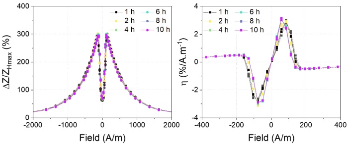
Fig. 1 $\Delta Z/Z$ ratios and field sensitivities $\eta$ of VITROVAC® 6025 I50 measured at frequency 10 MHz after keeping the sample at 200$^\circ$C for different time.
Acknowledgements
This work was supported by the projects APVV-19-0369, VEGA 2/0148/23 and JRP NOMAGRAD. We thank Dr. G. Herzer and T. Strache from Vacuumschmelze GmbH for providing us with stress annealed samples.
References
[1] G. V. Kurlyandskaya, V. M. Prida, B. Hernando, J. D. Santos, M. L. Sánchez, and M. Tejedor, “GMI sensitive element based on commercial Vitrovac® amorphous ribbon,” Sensors and Actuators A: Physical, vol. 110, no. 1–3. Elsevier BV, pp. 228–231, Feb. 2004. doi: 10.1016/j.sna.2003.09.044.
[2] M.-H. Phan and H.-X. Peng, “Giant magnetoimpedance materials: Fundamentals and applications,” Progress in Materials Science, vol. 53, no. 2. Elsevier BV, pp. 323–420, Feb. 2008. doi: 10.1016/j.pmatsci.2007.05.003.Speaker: Miloš Jakubčin (Institute of Experimental Physics SAS) -
16:00
Uncertainty Analysis of Traceable Measurements of Pulsed Magnetic Fields used in Magnetotherapy 2h
One of the practical applications of pulsed magnetic fields (PMF) is in magnetotherapy systems. These systems often generate low-frequency PMF for non-invasive therapy of muscles or bones. Some PMF system manufacturers use commercial teslameters with a Hall probe to measure the generated amplitude of the magnetic flux density $B_m$. However, the traceability and accuracy measurements of $B_m$ of PMF using a Hall probe is an issue. There are papers describing methods using various types of search coils or pick-up coils with a digital oscilloscope or a DAQ device [1] for this kind of measurement, but they offer no stated traceability or detailed uncertainty analysis. Integration of the induced voltage pulse using an integrator is needed in order to calculate the measured value of Bm. A method using a special PCB search coil [2] with a digital oscilloscope has been developed at CMI. The method has been tested on pulse magnetic field signals (Fig. 1) with repeating frequencies of 40 Hz and 140 Hz (generated $B_m$ value of about 2 mT and about 12 mT). This method can be used without using an integrator, and the $B_m$ value is determined directly from the sampled pulse parameters. However, the expanded uncertainty value of the measurement is quite high (about 40 $\%$ in the worst case for a $B_m$ value of about 2 mT using a DSO-X 4024A oscilloscope). A comparison was performed between the use of an 8-bit (DSO-X 4024A) and a 16-bit (PicoScope 5444D) digital oscilloscope. Further, the method was improved using a 3458A digital multimeter as a digitizer, which significantly reduced the expanded uncertainty of the measurement (about 3 $\%$ for a $B_m$ value of about 2 mT). The measurement results obtained using the 3458A multimeter were compared to the results obtained using digital oscilloscopes and also with measurements obtained by various teslameters with Hall probes. A description will be presented of the method, the results and a detailed uncertainty analysis using digital oscilloscopes and a 3458A multimeter.
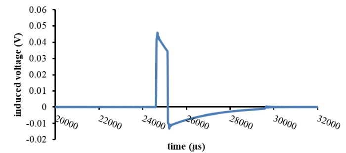
Fig. 1 Example of the PMF waveform - induced voltage from the PCB search coil at 40 Hz.References
[1] B. Zubrzak, P. Bieńkowski, “50 Hz pulse magnetic field measurements - metrological possibilities of magnetic field meters, ” Przegląd Elektrotechniczny, R. 94, No. 1, pp. 121-124, 2018. doi: 10.15199/48.2018.01.31
[2] M. Ulvr, “Design of PCB search coils for AC magnetic flux density measurement,” AIP Advances, vol. 8, no. 4. AIP Publishing, Oct. 17, 2017. doi: 10.1063/1.4991643.Speaker: Michal Ulvr (Czech Metrology Institute) -
16:00
Utilizing Bistable Glass-coated Microwires for Deformation Monitoring of Metal Structural Members 2h
Measuring changes in physical quantities without direct contact is still challenging in sensor applications. Especially in the case of structural member monitoring, it is quite difficult to substitute conventional electrical strain gauges with contactless technology.
A promising solution can be found in magnetically bistable glass-coated microwires. The small dimensions of microwires make it possible to attach them to different kinds of materials or even embed them in nonmetallic materials. The presented experimental approach of contactless monitoring is composed of two basic elements. The first element is the bistable glass-coated microwire, which can be considered as the passive part. The second part, also known as the active segment, is made of two coils – an excitation coil and a sensing coil. While the excitation coil generates an AC magnetic field necessary for the microwire's magnetic reversal process (excitation of the microwire), the sensing coil is used to capture the signal from the microwire. Since the microwire is sensitive to the applied mechanical stress, it can be used for contactless deformation monitoring [1].
Moreover, the magnetically bistable character of the glass-coated microwire allows the separation of the influence of additional parasitic external magnetic field from the deflection measurement. Because of that, the presented approach is suitable for contactless deformation monitoring of metallic materials with a ferromagnetic nature and in conditions with additional external magnetic field influence [2].
Acknowledgements
This work was supported by the Slovak projects APVV-15-0777, APVV-16-0079, Slovak VEGA grant No. 1/0129/20 and VEGA 1/0180/23.
References
[1] M. Al Ali, P. Platko, V. Bajzecerova, S. Kmet, L. Galdun, A. Spegarova, R. Varga, “Monitoring the strain of beech plywood using a bistable magnetic microwire,” Sens. Actuators A: Phys. 326, 112726, 2021. doi: 10.1016/j.sna.2021.112726.
[2] M. Al Ali, P. Platko, V. Bajzecerova, S. Kusnir, S. Kmet, S. Nalevanko, A. Spegarova, L. Galdun, R. Varga, “Application of bistable glass-coated microwire for monitoring and measuring the deformations of metal structural members,” Measurement 208, 112458, 2023. doi: 10.1016/j.measurement.2023.112458.Speaker: Ladislav Galdun (Center for Progressive Materials, Technology and Innovation Park, P.J. Safarik University in Kosice, Tr. SNP 1, 04001, Kosice, Slovakia) -
16:00
Validation of an Electromagnetic Loop Probe for Real-Time Diagnostic of Near-Field in Electrical Vehicle 2h
This study focuses on the validation of the probe used in the Near Field Scan (NFS) assessment of electric vehicles (EVs). The validation includes the evaluation of the antenna factor (AF) of the probe: the ratio of the induced voltage to the product of the magnetic field strength and the number of turns as well as the effective area in the loop, the selectivity, the sensitivity and the noise.
Precise measurements in a transverse electromagnetic (TEM) cell require comprehensive knowledge of the field distribution in the cell. This paper presents the configuration and procedure of a measurement to generate the distribution of electromagnetic fields in TEM cells appropriate for a loop probe and its effective behavior. The measurement data for 3 axes are obtained for the loop probe in a frequency range from 10 MHz to 1000 MHz using a Vector Network Analyzers (VNA), as shown in Fig. 1a. From measured transmission coefficient $S21$, the antenna factor is calculated by
$F_{aH} \, \left[\left(\frac{A}{m} \right)V \right] = \frac{H_{TEM}}{V_{out}}=\frac{\sqrt{\frac{P_{in}\cdot50}{Z_0h}}}{\sqrt{P_{out}\cdot50}} = \frac{1}{S21}\cdot\frac{1}{Z_{0}h}$
The results show a strong agreement with the theoretical calculations, especially at high frequencies. The antenna factor (AF) for the position shows slight variations, which is to be expected as the wavelength approaches the size of the loop probe at such frequencies. This results in the influence of the orientation of the probe and the effective loop circumference, as shown in Fig. 1b.
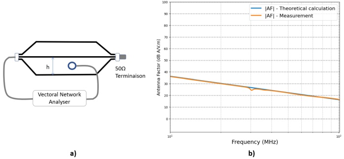
Fig. 1 a) Measurement Configuration In A TEM Cell. b) Magnetic Loop probe Antenna factor as a function of the frequency.
We arrange the investigated probes in two different directions within the cell and quantify the transmission parameter $S21$ in all scenarios. In a first orientation, the probe is positioned so that the surface of the loop is perpendicular to the Y-axis; in the second, as can be seen, the probe is rotated 90 degrees around the Z–axis, the measurement is totally changed with respect to the theoretical calculation.
References
[1] R. Trip and A. Buta, “TEM Cell Measurements in Automotive EMC : A Case Study,” 2022 Int. Symp. Electron. Telecommun., pp. 1–4, 2022, doi: 10.1109/ISETC56213.2022.10010216.
Speaker: Zaid Jabbar -
17:45
Coercivity Measurements of Complex-shaped Soft Magnetic Parts According to IEC 60404-7:2019 15m
Coercivity is not only one of the most fundamental properties of a soft magnetic material, but it is also very sensitive to structural changes of the material. Thus, since the introduction of the first coercimeters the measurement of the coercivity has become an important tool for the industry in quality control [1].
Due to the continued success the coercivity measurement techniques were first standardized in IEC 60404-7:1982 [2]. This standard has included the vibrating coil magnetometer [2,3], coercimeters with magnetic sensors near the sample as well as those with magnetic sensors outside the magnetizing coil [1,2].
After decades of only minor changes (e.g. in EU being integrated in EN 10330 [4,5]), a fully revised version was published in 2019. It reflected new findings in these measurements methods and also introduced the vibration sample magnetometer in an informative appendix [6]. However, even though it has been adapted as EN IEC 60404-7:2020 [7], not in all countries the new standard has yet been implemented (even not in EU). Among the users of these standards this results in a state of insecurity which method is in compliance with the new standard and what is the roadmap for introducing the standard on a national level.
This work will not only review the major changes of the new EN IEC 60404-7:2020 with a special focus on the challenges on measuring complex-shaped soft magnetic materials and addressing the roadmap for introduction of the new standard, but also will compare the new standard to other still valid national standards in the intermediate state.
References
[1] F. Foerster, Die schnelle und genaue Messung der Koerzitivkraft I, Archiv f. Techn. Messen, vol. 252-263,pp. 119–120, 1957, doi: 10.1524/teme.1957.252263.jg.119
[2] IEC 60404-7:1982, Magnetic materials – Part 7: Method of measurement of the coercivity of magnetic materials in an open magnetic circuit, 1982.
[3] H. Neumann, “Die Koerzitivkraft Hc , Definitionen und physikalische Meßgrundlagen,” Archiv f. Elektrotechnik, vol 39, 578–600, 1950. doi: 10.1007/BF01429757.
[4] EN 10330:2003, Magnetic materials – Method of measurement of the coercivity of magnetic materials in an open circuit, 2003.
[5] EN 10330:2015, Magnetic materials – Method of measurement of the coercivity of magnetic materials in an open circuit, 2015.
[6] IEC 60404-7:2019, Magnetic materials – Part 7: Method of measurement of the coercivity (up to 160 kA/m) of magnetic materials in an open magnetic circuit, 2019.
[7] EN IEC 60404-7:2020, Magnetic materials – Part 7: Method of measurement of the coercivity (up to 160 kA/m) of magnetic materials in an open magnetic circuit, 2020.Speaker: Markus Kuhnt
-
16:00
-
20:00
→
23:00
Conference DINNER 3h SOKRATES
SOKRATES
Doktora Kostlivého 576/1
-
08:00
→
09:00
-
-
09:00
→
10:30
THU: Session 7 Lecture Hall
Lecture Hall
Košice, Slovakia
Doktora Kostlivého 576/1Convener: Dr Tibor-Adrian Óvári (National Institute of Research and Development for Technical Physics, Iasi, Romania)-
09:00
Additive Manufacturing of Heusler-type Heat Exchangers for Solid State Refrigeration 30m
Existing societal challenges require advancing innovative, eco-friendly technologies and the capacity to manufacture 3D structures sustainably and profitably. Progress in caloric materials, such as magneto- or elasto-caloric compounds, as integral components of the forthcoming generation of energy-efficient devices, offer new opportunities for exploring potential breakthroughs in additive manufacturing. Metamagnetic shape memory alloys emerge as promising candidates for magnetic refrigeration due to their high entropy change through the first-order martensitic transformation. Nonetheless, it is essential to note that their crystalline phase destabilizes at elevated temperatures exceeding 300 $^{\circ}$C.
In this work, we formulated original inks and pastes tailored for cold extrusion printing techniques, enabling the fabrication of intricate 3D structures using high-performance NiMnSn-based magnetocaloric powders. A sustainable matrix of hydroxypropyl cellulose and deionized water as a solvent was used. The ink, comprising over 95 wt.$\%$ of powder, was carefully optimized to attain ideal viscosity, resulting in the capability to deposit a maximum of 250 layers with the utmost printing resolution (0.5 mm wall thickness).
The proposed post-processing for the printed structures involves two main steps: (i) specialized thermal treatments for desiccating the printed structures, eliminating the polymer via calcination, succeeded by sintering to achieve an all-metal structure, and (ii) nickel electrodeposition to protect the printed structure against corrosion. Furthermore, we demonstrate that incorrectly printed workpieces can be recycled by dissolving them in water, significantly minimizing material loss and improving the cost-effectiveness and environmental sustainability of the printing process.
Acknowledgements
The author gratefully thanks the support received from the Spanish Ministry of Science, Innovation and Universities through the grant number MCIN/AEI/10.13039/501100011033.
Speaker: Daniel Salazar (BCMaterials, Basque Center for Materials, Applications and Nanostructures, UPV/EHU Science Park, Leioa 48940, Spain) -
09:30
Influence of Electric Current in the Domain Wall Dynamics for Fe-based Amorphous Microwires 15m
The study of the propagation of a single domain wall (DW) is quite important for technological applications in order to understand and improve the operating features of devices based on DW logic. For that purpose, Fe-rich amorphous glass-coated microwires are excellent candidates as their magnetization process consists in the depinning of a single DW that propagates through the microwire at velocities than can be higher than 1 km/s [1]. Many works have been devoted to the dynamic behavior of the DW when an axial magnetic field is applied but only few for applied current [2,3]. In this work we have studied the dynamics of the DW when a pulse of current is applied.
The microwire here studied (Fe$_{75}$Si$_{10}$B$_{15}$, 18.6 $\mu$m of metallic nucleus, 21.6 $\mu$m total diameter and 42 cm length) shows an intrinsic torsion related to their manufacturing process, as a result of which the application of a current induces a change in the longitudinal component of magnetization (inverse Wiedemann effect). Depending on whether the orientation of the circular field is parallel or antiparallel to the $M\phi$ component of the domain, the application of a current to the microwire (constant for the duration of wall propagation) results in an increase or decrease in the velocity of the DW with respect to its value in absence of current (a bias DC magnetic field is applied as well).
Besides, the ability to induce wall movement has been shown under the action of only a current pulse applied to the wire when the pulse magnitude is above a certain threshold value (7.3 mA). The study of the dynamics of the wall has revealed the existence of two propagation regimes, depending on the magnitude of the current pulse, analogously to what has been reported in microwires for the dynamics of the wall within a magnetic field. In particular, for current pulse amplitudes below 10 mA, the velocity shows a dependence on the pulse width that can be described by a power law, corresponding to an intermittent movement of the wall as a consequence of the strong interaction with the defects, so analogous to what occurs in the low axial field regime. For higher amplitudes above 10 mA, the velocity increases linearly with the current, as also happens in the viscous regime of motion induced by axial field.
The mobility obtained in the case of the viscous regime turns out to be approximately 8 times less in the case of current-induced motion than in the case of movement induced by axial field, given the relationship between mobility and component of the magnetization on which the field acts and the preponderance of the anisotropy in the axial direction. Although it is not possible to exactly justify the relationship found between both mobilities (since both the component $M\phi$ as the damping coefficient can be modified as a result of the application of a circular field), it is expected that the mobility associated with the dynamics under axial field is greater than that corresponding to circular field, given the fundamentally axial orientation of the magnetoelastic anisotropy, related with the predominance of tensile stresses in most of the metallic core.
References
[1] H. Chiriac and T. A. Óvári, “Amorphous glass-covered magnetic wires: Preparation, properties, applications,” Progress in Materials Science, vol. 40, no. 5. Elsevier BV, pp. 333–407, Jan. 1996. doi: 10.1016/s0079-6425(97)00001-7.
[2] V. Zhukova, J. M. Blanco, A. Chizhik, M. Ipatov, and A. Zhukov, “Current induced domain wall propagation in Co-rich amorphous microwires,” AIP Advances, vol. 7, no. 5. AIP Publishing, Feb. 23, 2017. doi: 10.1063/1.4977495.
[3] S. Corodeanu, H. Chiriac, A. Damian, N. Lupu, and T.-A. Óvári, “Field and Current Controlled Domain Wall Propagation in Twisted Glass-Coated Magnetic Microwires,” Scientific Reports, vol. 9, no. 1. Springer Science and Business Media LLC, Apr. 10, 2019. doi: 10.1038/s41598-019-42352-1.Speaker: Rafael Perez del Real (Institute of Materials Science of Madrid, ICMM-CSIC) -
09:45
Magnetic Anisotropy Control in Thin Film and Magneto-Resistive Multilayer Devices via Oblique Incidence Deposition 15m
Flexible control over magnetic properties in thin films is essential for customization of magnetic devices for data storage, signal processing and especial sensor technology. Oblique incidence deposition (OID) offers the unique capability to prepare ultra-thin films with customized anisotropic surface morphologies and thus adjustable strength and orientation of uniaxial magnetic shape anisotropy simply via deposition at defined oblique orientation relative to the sample plane.
In the recent years we stepwise optimized and extended the OID approach in our group for customization of various magnetic thin film systems. It enabled us to realize single polycrystalline films with high uniaxial magnetic anisotropy, magnetic multilayers with arbitrary crossed magnetization axes for GMR and TMR sensor applications (Fig. 1a, [1-3]) and very recently single films with imprinted vertical spin spiral structures (Fig. 1b). Nuclear forward scattering of synchrotron radiation (NFS) was applied in the different projects to monitor the magnetization depth profile in these films with extra-ordinary spatial resolution which set the basis for further developments of the film structures. This contribution will give an overview on both OID projects (TMR sensors, imprinted vertical spin spirals) and related spin-structures identified via NFS as well as specialized OID coating equipment developed in our group (Fig. 1c).

Fig. 1 a) Schematic drawing of an OID-TMR layer stack. The magnetic response of the sensor to an external magnetic field and thus sensing functionality can be freely set via our OID approach. Uniaxial easy axes (red arrows) can be imprinted into both magnetic electrodes separately with adjustable strength of magnetic anisotropy via the coating process. b) Schematic drawing of a stabilized 90$^\circ$ vertical spin spiral structure in a 10 nm thin iron film. The OID coating parameters define the orientation of the top and bottom easy axes in the film and thus extension of magnetic spiral. c) Photo of our latest, self-made OID coating device for sputter deposition on larger objects.
References
[1] K. Schlage, L. Bocklage, D. Erb, J. Comfort, H. Wille, and R. Röhlsberger, “Spin‐Structured Multilayers: A New Class of Materials for Precision Spintronics,” Advanced Functional Materials, vol. 26, no. 41. Wiley, pp. 7423–7430, Sep. 08, 2016. doi: 10.1002/adfm.201603191.
[2] S. Willing, K. Schlage, R. Röhlsberger et al., “Novel Tunnel Magnetoresistive Sensor Functionalities via Oblique-Incidence Deposition,” ACS Applied Materials & Interfaces, vol. 13, no. 27. American Chemical Society (ACS), pp. 32343–32351, Jul. 02, 2021. doi: 10.1021/acsami.1c03084.
[3] K. Schlage et al., EP 2846334 B1 (2017), EP 3 588 591 A1 (2020), EP 3 587 619 A1 (2021).Speaker: Dr Kai Schlage (DESY) -
10:00
Magnetocaloric Effect in SrRuO3 Single Layer and Exchange Coupled BiFeO3-SrRuO3 Bilayer 15m
Harnessing extra degrees of freedom in magnetic oxides is of vital importance to bring new functionalities to cooling technology. The present study reports on the magnetocaloric effect (MCE) and magnetic exchange bias effect in the SrRuO$_{3}$ single layer and BiFeO$_{3}$/SrRuO$_{3}$ bilayers. MCE and exchange bias behaviors are found to be governed by Ru vacancies, structural distortions, and interfacial inter-diffusions. Additionally, the MCE is simulated using Maxwell's equations from both in-plane and out-of-plane magnetization data. The maximum entropy change ($|\Delta S|$) of 120 mJ/kg$\cdot$K and adiabatic temperature change ($\Delta T_{ad}$) of 0.028 K at a small field of 0.01 T are observed around the Curie temperatures ($T_{C}$) of SrRuO$_{3}$ layer in the out-of-plane directions. The variation in the maximum $|\Delta S|$ (70-120 mJ/kg$\cdot$K) and corresponding $T_{C}$ values (138-100 K) reveal that Ru vacancies can significantly contribute to tuning the MCE. Interestingly, BiFeO$_{3}$/SrRuO$_{3}$ bilayer structures are found to sustain not only MCE over a broad temperature range with different $\Delta S$ peaks but also exhibit a huge coercivity enhancement, making them attractive for improved on-chip cooling and spintronic devices.
Speaker: Murtaza Bohra (Mahindra University, India) -
10:15
Rapidly Annealed High-Bs Fe(Co)-Based Soft Magnetic Nanocrystalline Alloys for Applications at Elevated Temperatures 15m
Technological demand for soft magnetic materials capable of operation at high temperatures has led to an increased interest in FeCo-based nanocrystalline alloys. Magnetic components in various energy conversion devices and sensors are during their operation often exposed to high temperature environments, which could have a marked impact on their performance. Therefore, a better knowledge about stability of functional properties if the soft magnetic materials are used at elevated temperatures is of high importance for estimation of their application potential. In this work, the effects of rapid annealing (RA) on soft magnetic properties at elevated temperatures were investigated in series of high-Bs Fe-(Co)-B-(Cu) alloys prepared by planar flow casting. A special attention was given to rapid annealing technique that utilizes a compression of samples between pre-heated Cu blocks. This technique allows to obtain soft magnetic nanocrystalline alloys with reduced content of non-magnetic elements exhibiting attractive combination of high saturation magnetic flux density ($B_{s}$) and low coercivity ($H_{c}$) [1,2]. The as-quenched amorphous ribbons were subjected to rapid annealing for 0.5 s at temperatures between 480-500°C, which were identified as optimum RA heat treatment conditions. A more detailed description of the rapid annealing setup used in our study can be found in [3]. The second batch of amorphous ribbons was conventionally annealed (CA) in the vacuum furnace for 60 minutes at temperatures close to their first crystallization peak temperature determined by DSC calorimetry. We show that very high heating rates and short processing times during RA resulted in a formation of rather small nanocrystalline grains with typical sizes in the range of 10-15 nm. The observed grain refinement has led to a marked reduction of coercivity as compared to conventionally annealed samples Our main attention was focused on the characterization of soft magnetic properties of RA samples at elevated temperatures. The hysteresis loops were collected from room temperature (RT) up to 673 K using the Förster type B-H loop tracer with a built-in furnace placed inside the magnetically shielded room. Reference hysteresis loop were also collected at RT after each high temperature measurement. Our experiments revealed that rapidly annealed high-$B_{s}$ Fe-(Co)-B-(Cu) alloys exhibit very good thermal stability of soft magnetic characteristics up to 623 K, which makes them promising soft magnetic materials for applications at elevated temperatures.
Acknowledgements
This work was supported by the projects APVV-19-0369, VEGA 2/0148/23 and JRP NOMAGRAD.
References
[1] K. Suzuki, R. Parsons, B. Zang, K. Onodera, H. Kishimoto, and A. Kato, “Copper-free nanocrystalline soft magnetic materials with high saturation magnetization comparable to that of Si steel,” Applied Physics Letters, vol. 110, no. 1. 2017. doi: 10.1063/1.4973772.
[2] B. Kunca, J. Marcin, R Parsons, P. Švec, P. Švec sr., K. Suzuki, I. Škorvánek, “Soft magnetic performance of ultra-rapidly annealed high-Bs Fe-(Co)-B nanocrystalline alloys at elevated temperatures”, J. Alloy. Compd. vol. 911, 16503, 2022. doi: 10.1016/j.jallcom.2022.165033.
[3] B. Kunca, J.Marcin, P. Švec sr., I. Škorvánek, “Thermal stability and magnetic properties of the nanocrystalline (Fe64Co21B15)99Cu1 high-Bs alloy at elevated temperatures”, J. Magn. Magn. Mater. vol. 591, 171679, 2024. doi: 10.1016/j.jmmm.2023.171679.Speaker: Dr Ivan Škorvánek (Institute of Experimental Physics SAS)
-
09:00
-
10:30
→
11:00
Coffee break 30m MINERVA
MINERVA
Doktora Kostlivého 576/1 -
11:00
→
12:30
THU: Session 8 Lecture Hall
Lecture Hall
Košice, Slovakia
Doktora Kostlivého 576/1Convener: Tsuyoshi Uchiyama (Department of Electronics, Graduate School of Engineering; Nagoya University,)-
11:00
The Impact of Temperature on the Magnetic Properties and Magneto-Impedance Effect of Glass-coated Microwires 30m
Studies of temperature dependence of the Giant magnetoimpedance, GMI, effect become essentially relevant from the viewpoint of applications of magnetic wire inclusions embedded in multifunctional composite materials for non-destructive and non-contact stress and temperature monitoring [1]. Most of the few studies on temperature dependence of GMI were performed in thick amorphous wires without glass coating and in very limited temperature range [2]. Although the highest GMI effect is usually observed in Co-rich magnetic microwires, GMI effect of Fe-rich glass-coated microwires can be substantially improved by stress-annealing induced magnetic anisotropy [3].
We studied the temperature dependence of the magnetic properties and giant magnetoimpedance, GMI, effect in Co$_{69.2}$Fe$_{3.6}$Ni$_{1}$B$_{12.5}$Si$_{11}$Mo$_{1.5}$C$_{1.2}$ and Fe$_{75}$B$_{9}$Si$_{12}$C$_{4}$ glass-coated microwires, with nearly-zero and positive magnetostriction coefficient, respectively. The amorphous glass coated microwires were produced by the Taylor Ulitovsky technique and measured in as-prepared and annealed states. Remarkable change in the hysteresis loops and GMI effect is observed for both samples upon heating. Co$_{69.2}$Fe$_{3.6}$Ni$_{1}$B$_{12.5}$Si$_{11}$Mo$_{1.5}$C$_{1.2}$ microwires present a modification in the hysteresis loop shape upon heating that correlates with a change in the $\Delta Z/Z(H)$ dependencies. In as-prepared and most of the heat treated samples the hysteresis loop transformation from inclined to squared upon heating correlates with the change in $\Delta Z/Z(H)$ dependencies from double-peak to single-peak. However, the stress-annealed at 118 MPa samples present better thermal stability of the $\Delta Z/Z(H)$ dependencies and hysteresis loops. In all the studied samples an increase in the GMI ratio at 300 $^{\circ}$C was observed.
For as-prepared FeBSiC microwire a beneficial influence of the temperature on the GMI ratio is observed and hysteresis loops change of character from almost rectangular shape to inclined one. On the other hand, although GMI ratio improvement after stress-annealing (annealing temperature Tann= 325 $^{\circ}$C, stress applied during the annealing $\sigma$= 190MPa) decreases with the temperature increasing, temperature dependence can be tuned by the stress annealing conditions. Additionally, almost complete reversibility of the changes induced by the temperature is observed. The origin of the observed temperature dependences is discussed in terms of the Hopkinson effect, temperature dependence and relaxation of internal stresses, induced magnetic anisotropy, and temperature dependence of the magnetostriction coefficient.
References
[1] V. Zhukova et al., “Free Space Microwave Sensing of Carbon Fiber Composites With Ferromagnetic Microwire Inclusions,” IEEE Sensors Letters, vol. 8, no. 1. Institute of Electrical and Electronics Engineers (IEEE), pp. 1–4, Jan. 2024. doi: 10.1109/lsens.2023.3337071.
[2] J. Nabias, A. Asfour, and J.-P. Yonnet, “Temperature Dependence of Giant Magnetoimpedance in Amorphous Microwires for Sensor Application,” IEEE Transactions on Magnetics, vol. 53, no. 4. Institute of Electrical and Electronics Engineers (IEEE), pp. 1–5, Apr. 2017. doi: 10.1109/tmag.2016.2625841.
[3] P. Corte-Leon, V. Zhukova, J. M. Blanco, L. González-Legarreta, M. Ipatov, and A. Zhukov, “Stress-induced magnetic anisotropy enabling engineering of magnetic softness of Fe-rich amorphous microwires,” Journal of Magnetism and Magnetic Materials, vol. 510. Elsevier BV, p. 166939, Sep. 2020. doi: 10.1016/j.jmmm.2020.166939.Speaker: Paula Corte-León (University of Basque Country, UPV/EHU; University of Cambridge) -
11:30
Large Magnetoresistance in Magnetite Pellets 15m
The experimental evidence of large magnetoresistance in magnetite pellets is provided in this paper. Applying magnetic field along the length of the four-point probe resistivity monitoring, on the surface of a bulk magnetite pellet, results in elevated magnetoresistance change in the order of 100$\%$. Measurements were realized in $10^{-3}$ mbar vacuum with excitation currents from 0.1 A up to 0.5 A, with magnetic field from 0 mT up to 250 mT. After the transient decrease of resistance due to the increase of the carrier number because of the semiconducting nature of the magnetite pellets, the final resistance of the sample was dependent on the externally applied field. A typical response is illustrated in Figure 1. The reason for such drop of resistivity is the parallelization of the magnetic flux $B$ of the magnetite pellet with the excitation current, thus resulting in the reduction of the Lorentz force on the conducting carriers, reducing the Lorentz scattering effect.
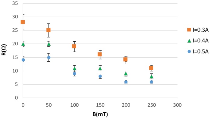
Fig. 1 Steady state resistance dependence of magnetite pellets on magnetic field, for different electric currents transmitted through the pellet.
Speaker: Prof. Evangelos Hristoforou (Sensors Lab, National TU of Athens) -
11:45
CMMFR Type GMI Gradiometer Based on Single Coil Feedback 15m
The Giant Magneto-Impedance effect, which changes impedance of amorphous wire in response to the magnetic fields, is used in highly sensitive magnetometers for measuring biomagnetic fields, electronic compasses, and other applications. GMI sensor face a trade-off between sensitivity and wide dynamic range. GMI sensors with sensitivity on the order of pico-tesla, suitable for biomagnetic measurements, are limited to dynamic ranges of a few micro-tesla or less. One approach to achieving high sensitivity and wide dynamic ranges is to use magnetic field feedback, which is produced by feedback coil placed around the GMI sensor. Feedback coil can be integrated with the pickup coil of the GMI sensor, a configuration known as single coil feedback. This integration can make the GMI sensor smaller compared to designs where the feedback coil is separate from the pickup coil [1]. A gradiometer, which uses two different GMI sensor as sensing and reference element respectively, can reduce common mode noise represented by the geomagnetic field. A gradiometer combined with magnetic feedback functions as a common-mode magnetic field rejection-type (CMMFR-type) GMI gradiometer, which can more effectively reduce common mode noise [2].
In this study, we report the achievement of single coil feedback CMMFR type GMI gradiometer and conform the reduction of magnetic noise floor (Fig.1).
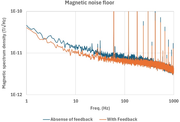
Fig. 1 Magnetic noise floor: Without Feedback and With Feedback.
References
[1] S. Gudoshnikov, N. Usov, A. Nozdrin, M. Ipatov, A. Zhukov, and V. Zhukova, “Highly sensitive magnetometer based on the off‐diagonal GMI effect in Co‐rich glass‐coated microwire,” physica status solidi (a), vol. 211, no. 5. Wiley, pp. 980–985, Feb. 14, 2014. doi: 10.1002/pssa.201300717.
[2] T. Takiya and T. Uchiyama, “Common-mode magnetic field rejection-type magneto-impedance gradiometer,” Journal of International Council on Electrical Engineering, vol. 7, no. 1. Informa UK Limited, pp. 1–6, Dec. 26, 2016. doi: 10.1080/22348972.2016.1271505.Speaker: Seiji Idachi (Uchiyama laboratory, Department of electronics, Nagoya University) -
12:00
High Sensitivity Digital GMI Sensors for Magnetic Communications 15m
The traditional wireless communication based on electromagnetic waves face difficulties when functioning in the harsh environments like underground, submarine or biological tissues. These difficulties are due to the rapid attenuation of the radio wave in these media. The communication method based on the magnetic field is the alternative solution for such scenarios because the magnetic field can penetrate the non-magnetic materials such as water, sol.
A conventional magnetic communication system is based on the magneto-induction principle. It is typically composed of transmitting and receiving coils that ensure the communication by magnetic coupling. At relatively low frequencies (a few tens of kilohertz) and for a small size of the receiving coil, the sensitivity of the receiver decreases. In this case, a dedicated high sensitivity magnetic sensor could advantageously replace the receiving coil. Under some conditions, it is expected that such magnetic sensors should allow better sensitivity than a conventional coil. This improvement in the sensitivity offers an increase in the communication distance while ensuring reduced dimensions of the device. These characteristics are favorable for integration into numerous mobile applications.
The aim of this paper is to present a proof of concept of using a high sensitivity digital Giant Magneto-Impedance (GMI) sensor as a receiver in a magnetic communication system. The architecture of the system is presented in Fig.1. The transmitter is composed of a solenoid which creates a modulated On-Off-Keying magnetic field signal h at a carrier frequency $f_m$ = 60 kHz. This field is measured by an off-diagonal GMI sensor with a working frequency $f_0$ = 1 MHz. The induced voltage $v_{coil}$ across the pick-up coil of the sensitive element is modulated twice at $f_0$ and $f_m$.
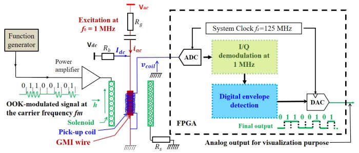
Fig. 1 Structure of the communication system.
A double amplitude-demodulation is digitally performed in real time to recover the binary sequence of the transmitted message. The first demodulation, at $f_0$, is based on a synchronous detection and the second, at $f_m$, involves a digital envelope detector.
The experimental results showing the reliable functioning of the system, through the transmission of ASCII codes, will be presented. A second study will provide a comprehensive comparison of performances between this system and conventional magnetic communication systems. These performances include sensitivity, bandwidth, transmission distance, signal to noise ratio, etc.
References
[1] M. Muzzammil, N. Ahmed, G. Qiao, I. Ullah and L. Wan, "Fundamentals and advancements of magnetic-Field communication for underwater wireless sensor networks", IEEE Transactions on Antennas and Propagation., vol. 68, no. 11, pp. 7555-7570, Nov. 2020. doi:10.1109/TAP.2020.3001451
Speaker: Miao XU (Univ. Grenoble Alpes, CNRS, Grenoble INP, G2Elab) -
12:15
Experimental Use of the Lidar Timing Circuit for Magnetometers Working with Time Conversion 15m
The aim of the ongoing research at our department in the field of magnetometers is the development of a compact modular magnetometric system operating with amorphous strips and microwires, used as a core. The motivation is in long-term research, development and testing of magnetometers with different types of control and processing electronics. The use of FPGA or CPLD devices for control and sensing electronics of relaxation and time-difference magnetometers has been verified.
The research has led over the years to the development of two types of fluxgate magnetometers. First of them is, the VEMA magnetometer developed and realized by the researchers at the Faculty of Aeronautics in cooperation with EDIS vvd. company. The second one, considering the current trend of reducing dimensions and power consumption in order to increase the performance of sensoric systems, considers the use of microwires as the core of the magnetometer due to their small size, low power consumption and good sensing properties [1,2].
Both types of magnetometric systems work with the conversion of magnetic field measurement to time measurement. For accurate time measurement in out experiments, the TDC7200 (time to digital converter) circuit designed for the LIDAR with the resolution of 55 ps has been used to measure the relaxation time and the time difference of our magnetometric systems. Generally, the device to measure the time would be a microcontroller, but in the case of 3 and more channels the advantage of synchronous timing would be lost. For this case, instead of a microcontroller, it is proficient to use a CPLD or an FPGA device, which, in addition to controlling the sensing and excitation electronics, also serves to control the TDC7200 circuits.
The paper builds on the knowledge obtained from the previously performed measurements in details described in [3] while the FPGA device is used to control the transistor bridge using optocouplers with timing adjustments. The paper presents results that were achieved during experiments focused on the improvement of the current devices’ precision and noise characteristics.
Acknowledgements
This research was funded by the ITMS2014+ 313011AUP1, 313011T557, APVV-18-0248, APVV-17-0184, KEGA 045TUKE-4/2022 and VEGA 1/0101/22 projects.
References
[1] Olivera et al., “Microwire-Based Sensor Array for Measuring Wheel Loads of Vehicles,” Sensors, vol. 19, no. 21. MDPI AG, p. 4658, Oct. 26, 2019. doi: 10.3390/s19214658.
[2] V. Zhukova, P. Corte-Leon, M. Ipatov, J. M. Blanco, L. Gonzalez-Legarreta, and A. Zhukov, “Development of Magnetic Microwires for Magnetic Sensor Applications,” Sensors, vol. 19, no. 21. MDPI AG, p. 4767, Nov. 02, 2019. doi: 10.3390/s19214767.
[3] P. Lipovský et al., “Relax-Type Magnetometer with Direct Optocoupler Relaxation,” Acta Physica Polonica A, vol. 137, no. 5. Institute of Physics, Polish Academy of Sciences, pp. 681–683, May 2020. doi: 10.12693/aphyspola.137.681.Speaker: Adam Polakovič (Technical University of Kosice - Faculty of Aeronautics)
-
11:00
-
12:30
→
14:00
LUNCH 1h 30m SOKRATES
SOKRATES
Doktora Kostlivého 576/1 -
14:00
→
15:30
THU: Session 9 Lecture Hall
Lecture Hall
Košice, Slovakia
Doktora Kostlivého 576/1Convener: Sébastien Saez (Normandie Univ, UNICAEN, ENSICAEN, CNRS, GREYC, 14000 Caen, France)-
14:00
Advanced 3D Magnetic Field Sensors Based on Spin Orbit Torque 30m
Magnetic field sensors are essential in our modern-day society, utilized in various applications including automobiles, mobile phones, and robotics. In this talk, I will discuss our work on magnetic field sensors that exploit spin orbit torque (SOT) to detect all three components of an external field with a single device. Initially, the focus will be on sensors where the signal is derived from the anomalous Hall effect. We demonstrate that active offset compensation for all three components is feasible through the SOT effect and a spinning current method applied to the anomalous Hall effect sensors. The SOT effect is induced by a spin-polarized current generated in a heavy metal (HM) layer via an electrical current, which then exerts a torque on a ferromagnetic (FM) layer positioned above the HM layer. This interaction modulates the magnetization of the free layer, enabling an offset-compensated sensor signal. Our results include various free layer designs aimed at achieving sensors with distinct linear regimes. One design utilizes a CoFeB free layer coupled with MgO, where the perpendicular anisotropy at the CoFeB/MgO interface compensates for shape anisotropy, resulting in sensors with linear ranges around 1 mT—ideal for detecting very low field strengths. Another design enhances the linear range using [W/CoFeB/MgO] multilayers. The presentation will conclude with the introduction of the first prototypes of spin orbit torque sensors that employ tunneling magnetic resistance for readout, significantly enhancing sensor sensitivity.
References
[1] S. Koraltan et al., “Skyrmionic device for three dimensional magnetic field sensing enabled by spin-orbit torques.” arXiv, 2024. doi: 10.48550/ARXIV.2403.16725.
Speaker: Prof. Dieter Suess (Austria) -
14:30
Multiscale Simulation of the Magneto-Impedance Effect 15m
The magnetoimpedance effect (MI) is an attractive phenomenon for several applications, such as magnetic field, stress, and temperature measurement, health monitoring and biological detection. To fully exploit the potential of these applications, it would be useful to develop numerical models able to predict the MI response under different conditions, accounting for materials with diverse properties and geometries. The impedance Z of a magnetic sample can be obtained by solving simultaneously Maxwell Equations (ME) and the Landau-Lifshitz-Gilbert (LLG) magnetization equation of motion. Except for highly symmetric and simple situations, obtaining an analytical solution for the impedance is not possible. One usual simplification is to assume a constant value for the magnetic permeability $\mu$. More elaborate approaches determine the value of the permeability as a function of the applied magnetic field using simple magnetization models. None of the models used So far accounts for the dependence of the permeability on the amplitude of the excitation field $h_{ac}$ created by the alternating current used to measure the impedance. This is certainly important, since the amplitude of $h_{ac}$ varies over the material, both the Ampere’s Law itself and the skin effect.
In this work, we model the MI effect from first principles, starting from fundamental magnetic properties. The method combines the numerical solution of the LLG equation using micromagnetic codes, with a finite element method to solve ME. Fig. 1 schematizes the process: Micromagnetic simulations enable us to determine the permeability for each bias field as a function of a wide range of excitation amplitudes and frequencies of $h_{ac}$. These results are then integrated into the finite element description of the ME, which solves the inter-dependency between $\mu$ and $h_{ac}$ in an auto-consistent way by obtaining the optimal values compatible with the solution of ME at each point. Thus, $Z$ is evaluated for different bias fields and frequencies. It is important to note the effect of ferromagnetic resonance is intrinsically included in the model, and its effects are clearly visible in $Z(H)$ curves. This calculation procedure can be used in special situations, such as under the effect of inhomogeneous fields. This is the case, for example, in the detection of magnetotactic bacteria, which generate a non-uniform stray field over the sensor volume. Using this model, a change of some milliohms is predicted in the MI signal by the presence of a single bacterium.

Fig. 1 Schematic representation of the modeling process: a) Permalloy (Ni$_{80}$Fe$_{20}$) thin film. b) Permeability for a frequency of 200 MHz as a function of $h_{ac}$ and $H_{bias}$. c) $Z(H)$ curves at different frequencies.
Speaker: Guillermo Gestoso (Universidad del País Vasco (UPV/EHU)) -
14:45
Error Correction of Analytical Field Expressions with Neural Networks 15m
Analytical expressions are favored for magnetic field calculations due to their speed compared to finite element simulations [1]. They excel in optimizing high-dimensional systems, allowing efficient exploration of parameter spaces, beneficial for designing cost-effective, robust, and accurate magnetic sensor systems [2]. Despite their usefulness, analytical expressions suffer from the idealized assumption of perfectly homogeneous magnetization. Even in high-quality rare earth magnets, the self-demagnetization effect, arising from the interaction of magnetic moments with the magnet's own field, is a fundamental limitation on the precision of high-precision applications relying on analytical field expressions [3].
We introduce a method using physics-based neural networks (NN) [4] to correct the self-demagnetization error in analytical field expressions. Unlike recent NN approaches [5], we base on the existing analytical solution and train our networks to rectify the errors (see Fig 1), resulting in significantly improved approximations compared to total field calculations with NNs. Our method notably enhances the accuracy of analytical field calculations, particularly in the near field near the magnetic surface, crucial for sensor applications with high amplitudes (see Fig. 2, ascending ordered errors for 1000 different cuboid magnet shapes simulated with assumed remanence polarization of 1T, linear material law and susceptibilities in (0,1), evaluated at different points with amplitudes >25mT). Moreover, the computational time of our NN method remains comparable to analytical expressions, preserving efficient computations even at scale.

Fig. 1 a) Illustration of our approach: Decomposing the total magnetic field into the analytical model's contribution and a neural network-based correction. b) Comparison of errors: Analytical solution, NN field computation, and our NN-correction to the analytical solution.
Acknowledgements
This work has been supported by Silicon Austria Labs (SAL), owned by the Republic of Austria, the Styrian Business Promotion Agency (SFG), the federal state of Carinthia, the Upper Austrian Research (UAR), and the Austrian Association for the Electric and Electronics Industry (FEEI).
References
[1] M. Ortner and L. G. Coliado Bandeira, “Magpylib: A free Python package for magnetic field computation,” SoftwareX, vol. 11. Elsevier BV, p. 100466, Jan. 2020. doi: 10.1016/j.softx.2020.100466.
[2] M. Ribeiro and M. Ortner, “Magnetic field shaping for improved 1-D linear position measurement,” 2015 9th International Conference on Sensing Technology (ICST). IEEE, Dec. 2015. doi: 10.1109/icsenst.2015.7438486.
[3] D. Cichon, R. Psiuk, H. Brauer, and H. Topfer, “A Hall-Sensor-Based Localization Method With Six Degrees of Freedom Using Unscented Kalman Filter,” IEEE Sensors Journal, vol. 19, no. 7. Institute of Electrical and Electronics Engineers (IEEE), pp. 2509–2516, Apr. 01, 2019. doi: 10.1109/jsen.2018.2887299.
[4] G. E. Karniadakis, I. G. Kevrekidis, L. Lu, P. Perdikaris, S. Wang, and L. Yang, “Physics-informed machine learning,” Nature Reviews Physics, vol. 3, no. 6. Springer Science and Business Media LLC, pp. 422–440, May 24, 2021. doi: 10.1038/s42254-021-00314-5.
[5] S. Pollok, N. Olden-Jørgensen, P. S. Jørgensen, and R. Bjørk, “Magnetic field prediction using generative adversarial networks,” Journal of Magnetism and Magnetic Materials, vol. 571. Elsevier BV, p. 170556, Apr. 2023. doi: 10.1016/j.jmmm.2023.170556.Speaker: Dr Florian Slanovc (Silicon Austria Labs (SAL)) -
15:00
A Finite Elements Scheme for the Optimization of Electromagnetic Energy Harvesters 15m
An energy harvester is a device that converts ambient energy from various sources such as light, vibration, or heat into electrical energy for powering electronic devices in situations where it is not practical to rely on conventional power sources, such as batteries or connections to the electrical grid. There are different types of energy harvesters, each designed to take advantage of specific energy sources, such as mechanical, radiation or thermal energy, among others. Particularly, vibrational energy harvesters transform small mechanical oscillations present in the environment, such as those generated by engines or vehicles, into electrical energy. Although piezoelectric materials are commonly used as active components in this type of harvesters, they show a decrease in efficiency for low-frequency vibrations (<100 Hz), typical of large structures such as bridges or the blades of windmills. In this context, magnetostrictive materials offer superior performance at these frequencies, where the conversion of mechanical to electrical energy is achieved through the Villari effect (variable magnetization and therefore an electromotive force induced in a receiving coil).
However, in order to optimize the converted power density these magnetostrictive vibrational energy harvesters, it is necessary to optimize both the vibrating frame where the magnetostrictive material is fixed, ensuring resonance at the appropriate frequencies, the static magnetic field and the receiving coil responsible for capturing the vibration-induced electric power. Consequently, an optimization problem arises, involving mechanical and electromagnetic aspects.
In this work, we propose the use of the finite element method (FEM) to solve partial differential equations in order to optimize a magnetostrictive vibrational energy harvester. This study focuses on magnetostrictive energy harvesters based on a U-shaped structure [1]. The vibrations generated in the U-shaped structure are transmitted to a magnetostrictive sheet composed of Gallium and Iron (GAFENOL), which is magnetized by permanent magnets (see Fig.1a). The partial differential equations to be addressed will include linear elasticity and Maxwell's equations. The coupling between the mechanical and electromagnetic system is carried out by adjusting the damping coefficients. As an example, Fig.1b shows the estimated electrical power versus frequency, at diferent magnet potitions (x).
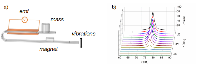
Fig. 1 Optimization of power changing the vibration frequency and magnet position.
Acknowledgements
This work is part of the project TED2021-130884B-I00, founded by “Ministerio de Ciencia e Innovación, Agencia Estatal de Investigación (AEI)” and European Union “Next Generation/PRTR”.
References
[1] T. Ueno, “Magnetostrictive low-cost high-performance vibration power generator,” Journal of Physics: Conference Series, vol. 1052. IOP Publishing, p. 012075, Jul. 2018. doi: 10.1088/1742-6596/1052/1/012075.
Speaker: Eneko Garayo Urabayen (Departamento de Ciencias & Institute for Advanced Materials and Mathematics INAMAT2. UPNA) -
15:15
Modelling and Optimization of a 2-terminal EMR Current Limiter 15m
Extraordinary magnetoresistance (EMR) sensors are geometry-dependent 4-terminal devices based on high-conductivity semiconductors and metal inclusions, that can achieve over $10^6\,\%$ magnetoresistance ratios [1,2]. The origin of such effect can be explained by Lorentz force, rewriting the conductivity tensor of the semiconductor with a magnetic field dependence. Deviations of the current path result in charge accumulation in the semiconductor, giving rise to incredibly high voltage differences.
In this work, this effect is employed for passive current limiting applications with a 2-terminal device. With the possibility to integrate a magnetic circuit in the current path, the rise in current will create a field on the EMR device, in turn increasing its resistance and thus limiting the current overshoot and its plateau levels [3]. Investigations of the analytical model of such device shows that the maximum achievable MR ratio is $\mu^{2}B^{2}$, where $\mu$ is the charge-carrier mobility of the semiconductor and $B$ is the magnitude of the applied magnetic field. Contrary to the 4-terminal sensor, metal inclusions do not improve the current limiter performance, and charge-accumulation at the edges degrades the obtained MR. The model indicates that this can be mitigated by engineering the geometry of the device, increasing the dimension parallel to the deviated current path. To approach the theoretical limit, the length of the device must be $\mu B$ times its thickness. We also present another solution to avoid charge-accumulation by short-circuiting the semiconductor edges, improving the MR without changing the device geometry. Another known negative influence on MR is the contact resistivity between the semiconductor and the metal electrodes [4]. The present work also proposes a way of minimizing this by tweaking the device geometry.
In current limiter applications, it is the current of the main circuit itself that passes through the device, and not a small bias current as it is the case in sensor applications. Electric current levels can reach units of amperes, and as high current passes through the EMR element, resistive power dissipation becomes relevant. Electric and thermal simulations with finite element method (COMSOL) in 3D for different device sizes corroborate the analytical model and are used to investigate resistance variations and Joule heating.
Acknowledgements
This work has been jointly supported by Eaton and Silicon Austria Labs, owned by the Republic of Austria, the Styrian Business Promotion Agency, the federal state of Carinthia, the Upper Austrian Research and the Austrian Association for the Electric and Electronics Industry.
References
[1] S. A. Solin, T. Thio, D. R. Hines, and J. J. Heremans, “Enhanced Room-Temperature Geometric Magnetoresistance in Inhomogeneous Narrow-Gap Semiconductors,” Science, vol. 289, no. 5484. American Association for the Advancement of Science (AAAS), pp. 1530–1532, Sep. 2000. doi: 10.1126/science.289.5484.1530.
[2] J. Sun and J. Kosel, “Extraordinary Magnetoresistance in Semiconductor/Metal Hybrids: A Review,” Materials, vol. 6, no. 2. MDPI AG, pp. 500–516, Feb. 13, 2013. doi: 10.3390/ma6020500.
[3] P. Kopejtko, “Current controlling element based on saturation of a magnetic circuit”, EP Patent EP3 961 925A1, Mar,. 2022
[4] J. Sun and J. Kosel, “Finite Element Analysis on the Influence of Contact Resistivity in an Extraordinary Magnetoresistance Magnetic Field Micro Sensor,” Journal of Superconductivity and Novel Magnetism, vol. 25, no. 8. Springer Science and Business Media LLC, pp. 2749–2752, Aug. 06, 2011. doi: 10.1007/s10948-011-1256-8.Speaker: Dr Luiz Enger (Silicon Austria Labs GmbH)
-
14:00
-
15:30
→
16:00
Coffee break 30m MINERVA
MINERVA
Doktora Kostlivého 576/1 -
16:00
→
16:15
Closing Ceremony 15m Lecture Hall
Lecture Hall
Košice, Slovakia
Doktora Kostlivého 576/1 -
16:15
→
16:30
Farewell 15m MINERVA
MINERVA
Doktora Kostlivého 576/1
-
09:00
→
10:30
